CLIMATE CONTROL SEAT SYSTEM TERMINALS OF ECU
-
CHECK FRONT CLIMATE CONTROL ECU LH

-
Disconnect the e34 and e114 ECU connectors.
-
Measure the voltage and resistance according to the value(s) in the table below.
Terminal No. (Symbols) Wiring Color Terminal Description Condition Specified Condition e34-1 (IG) - Body ground P - Body ground Power source Power switch on (IG) 11 to 14 V Power switch off Below 1 V e34-2 (SYSB) - Body ground R - Body ground Power source Always 11 to 14 V e34-12 (GND) - Body ground W-B - Body ground Ground Always Below 1 Ω e34-13 (LIN) - Body ground L - Body ground LIN line Always 10 kΩ or higher -
Reconnect the e34 and e114 ECU connectors.
-
Measure the voltage and resistance according to the value(s) in the table below.
Terminal No. (Symbols) Wiring Color Terminal Description Condition Specified Condition e114-1 (B) - Body ground Y - Body ground Power supply for seat heater Power switch on (IG)
Climate control switch OFF
Below 1 V Power switch on (IG)
Climate control switch Max. WARM
11 to 14 V e114-6 (H5) - Body ground P - Body ground Seat heater temp signal Power switch off Below 1 V Power switch on (IG) 1 to 4 V e114-7 (HS) - Body ground L - Body ground Seat heater temp signal ground Always Below 1 Ω e34-4 (BFC+) - Body ground P - Body ground Climate fan motor signal (for seat cushion) Power switch off Below 1 V Power switch on (IG) 11 to 14 V e34-5 (BCS) - Body ground BR - Body ground Climate fan motor signal (for seat cushion) Power switch on (IG)
Climate control switch OFF
Below 1 V Power switch on (IG)
Climate control switch ON (fan position)
3 to 8 V e34-6 (BFC-) - Body ground GR - Body ground Climate fan motor signal (for seat cushion) Always Below 1 Ω e34-7 (TDC-) - e34-8 (TDC+) R - Y Power supply for seat cushion
Peltier element (COOL)
Power switch on (IG)
Climate control switch OFF
Below 1 V Power switch on (IG)
Climate control switch Max. COOL
Pulse generation (see waveform) e34-14 (V5L) - Body ground LG - Body ground Climate control switch signal Power switch on (IG) 5 V e34-15 (VGL) - Body ground G - Body ground Climate control switch signal ground Always Below 1 Ω e34-16 (TCS) - Body ground R - Body ground Climate controller temp signal ground (for seat cushion) Always Below 1 Ω e34-17 (TBS) - Body ground L - Body ground Climate controller temp signal ground (for seatback) Always Below 1 Ω e34-18 (VSL) - Body ground W - Body ground Climate control switch signal Power switch on (IG)
Climate control switch Max. COOL
Below 1 V Power switch on (IG)
Climate control switch Max. WARM
5 V e34-19 (TC5) - Body ground V - Body ground Climate controller temp signal (for seat cushion) Power switch off Below 1 V Power switch on (IG) 1 to 4 V e34-20 (TB5) - Body ground SB - Body ground Climate controller temp signal (for seatback) Power switch off Below 1 V Power switch on (IG) 1 to 4 V e34-21 (INDL) - Body ground B - Body ground Illuminate signal Power switch on (IG)
Climate control switch OFF
11 to 14 V Power switch on (IG)
Climate control switch ON
Below 1 V -
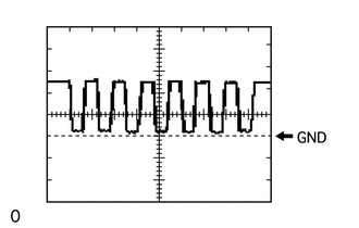
Using an oscilloscope, check waveform.
Item Content Terminal No. (Symbols) e34-7 (TDC-) - e34-8 (TDC+) Tool Setting 5 V/DIV., 20 ms/DIV. Condition Power switch on (IG)
Climate control switch Max. COOL
-
-
CHECK FRONT CLIMATE CONTROL ECU RH
-
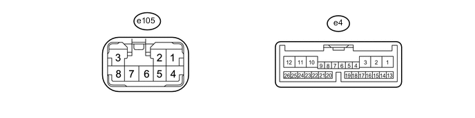
Disconnect the e105 and e4 ECU connectors.
-
Measure the voltage and resistance according to the value(s) in the table below.
Terminal No (.Symbols) Wiring Color Terminal Description Condition Specified Condition e4-1 (IG) - Body ground Y*1 - Body ground
GR*2 - Body ground
Power source Power switch on (IG) 11 to 14 V Power switch off Below 1 V e4-2 (SYSB) - Body ground W - Body ground Power source Always 11 to 14 V e4-11 (VER) - Body ground W-B - Body ground Ground Always Below 1 Ω e4-12 (GND) - Body ground W-B - Body ground Ground Always Below 1 Ω e4-13 (LIN) - Body ground L - Body ground LIN line Always 10 kΩ or higher -
Reconnect the e105 and e4 ECU connectors.
-
Measure the voltage and resistance according to the value(s) in the table below.
Terminal No. (Symbols) Wiring Color Terminal Description Condition Specified Condition e105-1 (B) - Body ground Y - Body ground Power supply for seat heater Power switch on (IG)
Climate control switch OFF
Below 1 V Power switch on (IG)
Climate control switch Max. WARM
11 to 14 V e105-6 (H5) - Body ground P - Body ground Seat heater temp signal Power switch off Below 1 V Power switch on (IG) 1 to 4 V e105-7 (HS) - Body ground L - Body ground Seat heater temp signal ground Always Below 1 Ω e4-4 (BFC+) - Body ground P - Body ground Climate fan motor signal (for seat cushion) Power switch off Below 1 V Power switch on (IG) 11 to 14 V e4-5 (BCS) - Body ground BR - Body ground Climate fan motor signal (for seat cushion) Power switch on (IG)
Climate control switch OFF
Below 1 V Power switch on (IG)
Climate control switch ON (fan position)
3 to 8 V e4-6 (BFC-) - Body ground GR - Body ground Climate fan motor signal (for seat cushion) Always Below 1 Ω e4-7 (TDC-) - e4-8 (TDC+) BE - Y Power supply for seat cushion
Peltier element (COOL)
Power switch on (IG)
Climate control switch OFF
Below 1 V Power switch on (IG)
Climate control switch Max. COOL
Pulse generation (see waveform) e4-14 (V5R) - Body ground LG - Body ground Climate control switch signal Power switch on (IG) 5 V e4-15 (VGR) - Body ground G - Body ground Climate control switch signal ground Always Below 1 Ω e4-16 (TCS) - Body ground R - Body ground Climate controller temp signal ground (for seat cushion) Always Below 1 Ω e4-17 (TBS) - Body ground L - Body ground Climate controller temp signal ground (for seatback) Always Below 1 Ω e4-18 (VSR) - Body ground W - Body ground Climate control switch signal Power switch on (IG)
Climate control switch Max. COOL
Below 1 V Power switch on (IG)
Climate control switch Max. WARM
5 V e4-19 (TC5) - Body ground V - Body ground Climate controller temp signal (for seat cushion) Power switch off Below 1 V Power switch on (IG) 1 to 4 V e4-20 (TB5) - Body ground SB - Body ground Climate controller temp signal (for seatback) Power switch off Below 1 V Power switch on (IG) 1 to 4 V e4-21 (INDR) - Body ground B - Body ground Illuminate signal Power switch on (IG)
Climate control switch OF
11 to 14 V Power switch on (IG)
Climate control switch ON
Below 1 V Tech Tips
-
*1: for LHD
-
*2: for RHD
-
-
Using an oscilloscope, check waveform.
Item Content Terminal No. (Symbols) e4-7 (TDC-) - e4-8 (TDC+) Tool Setting 5 V/DIV., 20 ms/DIV. Condition Power switch on (IG)
Climate control switch Max. COOL
-
-
CHECK REAR SEAT CLIMATE CONTROL ECU RH
-
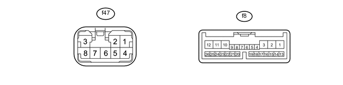
Disconnect the f47 and f8 ECU connectors.
-
Measure the voltage and resistance according to the value(s) in the table below.
Terminal No (.Symbols) Wiring Color Terminal Description Condition Specified Condition f8-1 (IG) - Body ground Y - Body ground Power source Power switch on (IG) 11 to 14 V Power switch off Below 1 V f8-2 (SYSB) - Body ground G - Body ground Power source Always 11 to 14 V f8-11 (VER) - Body ground W-B - Body ground Ground Always Below 1 Ω f8-12 (GND) - Body ground W-B - Body ground Ground Always Below 1 Ω f8-13 (LIN) - Body ground V - Body ground LIN line Always 10 kΩ or higher -
Reconnect the f47 and f8 ECU connectors.
-
Measure the voltage and resistance according to the value(s) in the table below.
Terminal No. (Symbols) Wiring Color Terminal Description Condition Specified Condition f47-1 (AMP) - Body ground L - Body ground Power supply for seat heater Power switch on (IG)
Climate control switch OFF
Below 1 V Power switch on (IG)
Climate control switch Max. WARM
11 to 14 V f47-6 (H5) - Body ground BR - Body ground Seat heater temp signal Power switch off Below 1 V Power switch on (IG) 1 to 4 V f47-7 (HS) - Body ground P - Body ground Seat heater temp signal ground Always Below 1 Ω f8-4 (BFC+) - Body ground W - Body ground Climate fan motor signal (for seat cushion) Power switch off Below 1 V Power switch on (IG) 11 to 14 V f8-5 (BCS) - Body ground V - Body ground Climate fan motor signal (for seat cushion) Power switch on (IG)
Climate control switch OFF
Below 1 V Power switch on (IG)
Climate control switch (fan position)
3 to 8 V f8-6 (BFC-) - Body ground BE - Body ground Climate fan motor signal (for seat cushion) Always Below 1 Ω f8-7 (TDC-) - f8-8 (TDC+) W - Y Power supply for seat cushion
Peltier element (COOL)
Power switch on (IG)
Climate control switch OFF
Below 1 V Power switch on (IG)
Climate control switch Max. COOL
Pulse generation (see waveform) f8-16 (TCS) - Body ground B - Body ground Climate controller temp signal ground (for seat cushion) Always Below 1 Ω f8-17 (TBS) - Body ground B - Body ground Climate controller temp signal ground (for seatback) Power switch on (IG)
Climate control switch OFF
Below 1 Ω f8-19 (TC5) - Body ground L - Body ground Climate controller temp signal (for seat cushion) Power switch off Below 1 V Power switch on (IG) 1 to 4 V f8-20 (TB5) - Body ground L - Body ground Climate controller temp signal (for seatback) Power switch off Below 1 V Power switch on (IG) 1 to 4 V f8-24 (BFB+) - Body ground G - Body ground Climate fan motor signal (for seatback) Power switch off Below 1 V Power switch on (IG) 11 to 14 V f8-25 (BBS) - Body ground Y - Body ground Climate fan motor signal (for seatback) Power switch on (IG)
Climate control switch OFF
Below 1 V Power switch on (IG)
Climate control switch ON (fan position)
4 to 7 V f8-26 (BFB-) - Body ground GR - Body ground Climate fan motor signal (for seatback) Always Below 1 Ω -
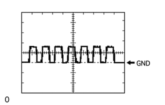
Using an oscilloscope, check waveform.
Item Content Terminal No. (Symbols) f8-7 (TDC-) - f8-8 (TDC+) Tool Setting 500 mV/DIV., 200 ms/DIV. Condition Power switch on (IG)
Climate control switch Max. COOL
-
-
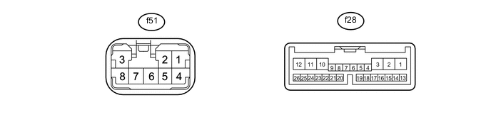
CHECK REAR SEAT CLIMATE CONTROL ECU LH
-
Disconnect the f51 and f28 ECU connectors.
-
Measure the voltage and resistance according to the value(s) in the table below.
Terminal No (Symbols.) Wiring Color Terminal Description Condition Specified Condition f28-1 (IG) - Body ground P - Body ground Power source Power switch on (IG) 11 to 14 V Power switch off Below 1 V f28-2 (SYSB) - Body ground V - Body ground Power source Always 11 to 14 V f28-12 (GND) - Body ground W-B - Body ground Ground Always Below 1 Ω f28-13 (LIN) - Body ground V - Body ground LIN line Always 10 kΩ or higher -
Reconnect the f51 and f28 ECU connectors.
-
Measure the voltage and resistance according to the value(s) in the table below.
Terminal No. (Symbols) Wiring Color Terminal Description Condition Specified Condition f51-1 (AMP) - Body ground L - Body ground Power supply for seat heater Power switch on (IG)
Climate control switch OFF
Below 1 V Power switch on (IG)
Climate control switch Max. WARM
11 to 14 V f51-9 (H5) - Body ground BR - Body ground Seat heater temp signal Power switch off Below 1 V Power switch on (IG) 1 to 4 V f51-10 (HS) - Body ground P - Body ground Seat heater temp signal ground Always Below 1 Ω f28-4 (BFC+) - Body ground W - Body ground Climate fan motor signal (for seat cushion) Power switch off Below 1 V Power switch on (IG) 11 to 14 V f28-5 (BCS) - Body ground V - Body ground Climate fan motor signal (for seat cushion) Power switch on (IG)
Climate control switch OFF
Below 1 V Power switch on (IG)
Climate control switch ON (fan position)
3 to 8 V f28-6 (BFC-) - Body ground BE - Body ground Climate fan motor signal (for seat cushion) Always Below 1 Ω f28-7 (TDC-) - f28-8 (TDC+) W - Y Power supply for seat cushion
Peltier element (COOL)
Power switch on (IG)
Climate control switch OFF
Below 1 V Power switch on (IG)
Climate control switch Max. COOL
Pulse generation (see waveform) f28-16 (TCS) - Body ground B - Body ground Climate controller temp signal ground (for seat cushion) Power switch on (IG)
Climate control switch OFF
Below 1 Ω f28-17 (TBS) - Body ground B - Body ground Climate controller temp signal ground (for seatback) Power switch on (IG)
Climate control switch OFF
Below 1 Ω f28-19 (TC5) - Body ground L - Body ground Climate controller temp signal (for seat cushion) Power switch off Below 1 V Power switch on (IG) 1 to 4 V f28-20 (TB5) - Body ground L - Body ground Climate controller temp signal (for seatback) Power switch off Below 1 V Power switch on (IG) 1 to 4 V f28-24 (BFB+) - Body ground G - Body ground Climate fan motor signal (for seatback) Power switch off Below 1 V Power switch on (IG) 11 to 14 V f28-25 (BBS) - Body ground Y - Body ground Climate fan motor signal (for seatback) Power switch on (IG)
Climate control switch OFF
Below 1 V Power switch on (IG)
Climate control switch ON (fan position)
4 to 7 V f28-26 (BFB-) - Body ground GR - Body ground Climate fan motor signal (for seatback) Always Below 1 Ω -
Using an oscilloscope, check waveform.
Item Content Terminal No. (Symbols) f28-7 (TDC-) - f28-8 (TDC+) Tool Setting 500 mV/DIV., 200 ms/DIV. Condition Power switch on (IG)
Climate control switch Max. COOL
-