INNER REAR VIEW MIRROR ADJUSTMENT

CAUTION / NOTICE / HINT
Tech Tips
-
The inner rear view mirror assembly (with adaptive high beam camera) is replaced or removed and installed.
-
When the windshield of a vehicle equipped with the adaptive high beam system is replaced due to a rock, etc. hitting the windshield.
-
DTC B2454 (Camera Optic Axis Initialization Incomplete) is detected.
Perform adaptive high beam camera beam axis initialization in the following conditions. It is not necessary to perform initialization if the adaptive high beam system ECU or other parts related to the adaptive high beam system are replaced.
PROCEDURE
-
ADJUST ADAPTIVE HIGH BEAM CAMERA BEAM AXIS
- SST
- 09870-50020 ( 09871-05010, 09871-05020 )
- 09870-60000 ( 09870-60010 )
-
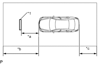
Text in Illustration *1 SST (Target) *a 900 mm *b 1 m or more *c 1 m or more (as much as possible) Perform this in a workplace that has a roof. Also, drive the vehicle headfirst into the workplace and set the target in the back.
Note
-
Perform this procedure on a level surface.
-
Perform this procedure indoors, as it is easily affected by the weather.
-
Perform this procedure in an area not affected by lighting.
-
Do not tilt the mirror excessively.
-
Do not illuminate the headlights.
-
Have one person sit in the driver seat while performing this procedure.
-
-
Beam Axis Learning Preparation
-
Move the vehicle to a level surface.
-
Check that the engine oil is at the specified amount.
-
Check that the coolant is at the specified amount.
-
Check that the spare tire is in place (for vehicles with a spare tire).
-
Check that the standard tools are in place.
-
Make sure nobody gets into the vehicle.
-
Do not put any extra load on the vehicle.
-
Adjust the tire pressures to the specified pressure Click here.
-
Clean the front windshield glass.
-
Make sure that the AHS camera of the inner rear view mirror assembly is not dirty.
Tech Tips
If the lens of the AHS camera is dirty, apply a small amount of lens cleaner to a clean, soft cloth and clean the lens.
-
-
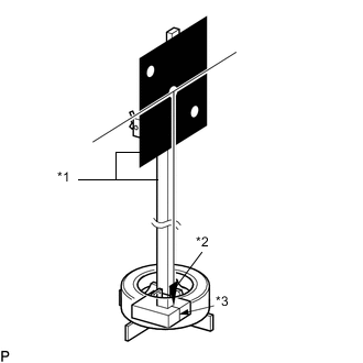
Text in Illustration *1 SST *2 Weight *3 Alignment Line Hang a weight with a pointed tip from the center of the target (SST). Then, attach the target to the reflector so that the weight aligns with the alignment line of the SST (laser radar adjusting reflector).
- SST
- 09870-50020 ( 09871-05010, 09871-05020 )
- 09870-60000 ( 09870-60010 )
Note
-
Perform this procedure as accurately as possible.
-
Attach the target so that it is horizontal to the ground.
-
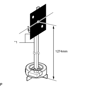
Text in Illustration *1 SST Move the reflector up and down to position the center of the target at the height shown in the illustration, and fix it in place.
- SST
- 09870-50020 ( 09871-05010, 09871-05020 )
- 09870-60000 ( 09870-60010 )
Note
Perform this procedure as accurately as possible.
-
Target placement point measurement
Note
-
Perform this procedure as accurately as possible.
-
Make sure there are no reflective materials or natural light coming from behind the target (directed towards the sensor).
-
Block out any natural light coming from behind the target (block windows, etc.).
-
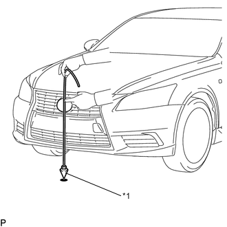
Text in Illustration *1 Weight From the center of the front bumper (center of the emblem), hang a weight with a pointed tip, and mark the front bumper center point A on the ground.
-
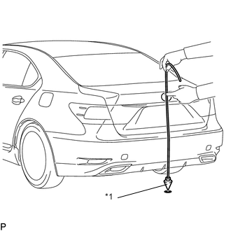
Text in Illustration *1 Weight From the center of the rear bumper (center of the emblem), hang a weight with a pointed tip, and mark the rear bumper center point B on the ground.
-
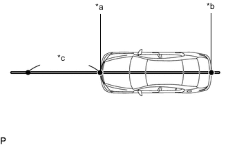
Text in Illustration *a Point A *b Point B *c 1 m or more Draw a line that connects points A and B on the ground, and extend the line approximately 1 m (3.28 ft.) beyond the front of the vehicle.
-
Mark placement point 1 900 mm (6. 233in.) from the front bumper center point A.
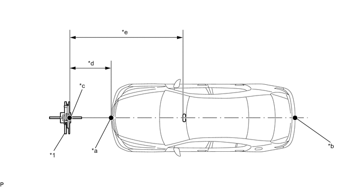
Text in Illustration *1 SST (Target) - - *a Point A *b Point B *c Point C (Target Placement Point 1) *d 900mm *e 3040mm - -
-
-
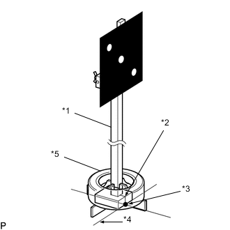
Text in Illustration *1 SST (Laser Radar Adjusting Reflector) *2 Alignment Line *3 Point C *4 Target Placement Line *5 Old Tire Align the SST (laser radar adjusting reflector) with the target placement line, align the alignment line with placement point 1 (point C), and fix the target in place as shown in the illustration using an old tire, etc. to prevent it from falling.
- SST
- 09870-50020 ( 09871-05010, 09871-05020 )
- 09870-60000 ( 09870-60010 )
-
Target Light Permeability Test
-
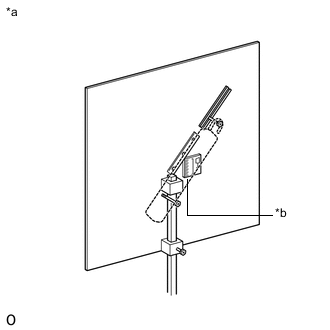
Text in Illustration *a Backside of Target *b Portable Light Placement Area After placing the target, place a portable light behind the target as shown in the illustration.
-
Turn on the light, and adjust its position so that the 3 points shown in the OK illustration are at the same brightness level (the points are red).

Note
Use a fluorescent light and make sure the output is between 10 and 27 W.
-
-
AHS Camera Beam Axis Adjustment
-
Enter the following menus: AHS / Utility / AHS Camera Optic Axis Adjustment
-
Follow the instructions on the screen, and press [Next] after turning the engine switch on (IG) (with the engine off).
-
Check that the AHS camera beam axis adjustment deviation amount is displayed. Then follow the instructions on the screen and press [Next].
-
Once the AHS camera beam axis adjustment completes, AHS Camera Optic Axis Adjustment is complete is displayed on the screen. Press [Exit] to finish the AHS camera beam axis adjustment.
Note
-
Check that DTC B2454 (Camera Optic Axis Initialization Incomplete) and DTC B2471 (Camera Optic Axis Correction Malfunction) are not output to finish the adjustment.
-
If [Do you want to exit adaptive high beam Camera Optic Axis Adjustment] is displayed, press Yes, confirm the conditions below, turn the engine switch on (IG) (with the engine off) and perform the adjustment again.
-
Check that the target is at the correct height.
-
Check that the distance between the vehicle (adaptive high beam camera) and target is correct.
-
Make sure there are no reflective materials or natural light coming from behind the target (directed towards the sensor).
-
Block out any natural light coming from behind the target (block windows, etc.).
-
The light permeability of the target is appropriate.
-
Illumination is turn off.
-
-