POWER MIRROR CONTROL SYSTEM Mirror Heater does not Operate with Rear Defogger Switch
SYSTEM DESCRIPTION
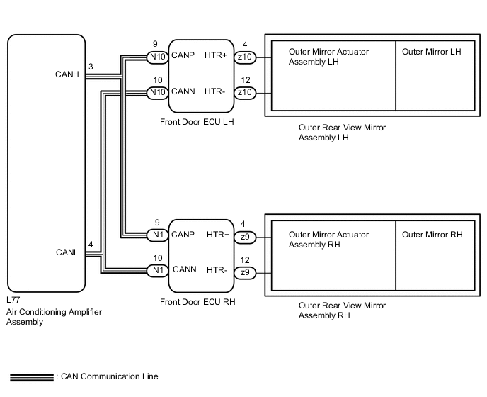
The mirror heater operates when the following conditions are met: 1) the air conditioning amplifier sends a rear defogger switch signal through the CAN communication line to the front door ECU LH and RH, and 2) the defogger operates.
WIRING DIAGRAM
PROCEDURE
-
CHECK DTC
-
Use the intelligent tester to check if the CAN communication system is functioning normally.
Result Result Proceed to CAN DTC is not output A CAN DTC is output (for LHD) B CAN DTC is output (for RHD) C
B 
GO TO CAN COMMUNICATION SYSTEM Click here
C
GO TO CAN COMMUNICATION SYSTEM Click here
A 
-
-
CHECK DEFOGGER SYSTEM
-
Check that the defogger operates normally.
OK Defogger operates normally.
NG
GO TO WINDOW DEFOGGER SYSTEM Click here
OK
-
-
PERFORM ACTIVE TEST USING INTELLIGENT TESTER (MIRROR HEATER FUNCTION)
-
Select the Active Test, use the intelligent tester to generate a control command, and then check the mirror heater function.
Driver Door Tester Display Test Part Control Range Diagnostic Note Mirr Heater Mirror heater operation OFF / ON - Passenger Door Tester Display Test Part Control Range Diagnostic Note Mirr Heater Mirror heater operation OFF / ON - Result Result Proceed to Outer rear view mirror (for driver side) does not operate normally A Outer rear view mirror (for passenger side) does not operate normally B Outer rear view mirror (for driver side) and outer rear view mirror (for passenger side) operates normally C
B 
INSPECT OUTER REAR VIEW MIRROR ASSEMBLY (for Passenger Side) Click here
C
REPLACE AIR CONDITIONING AMPLIFIER Click here
A
-
-
INSPECT OUTER REAR VIEW MIRROR ASSEMBLY (for Driver Side)
-
for LHD:
-
Remove the outer rear view mirror LH Click here.
-
Measure the resistance according to the value(s) in the table below.
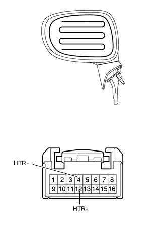
Standard resistance Tester Connection Condition Specified Condition 4 (HTR+) - 12 (HTR-) 25°C (77°F) 3.6 to 4.8 Ω -
Apply battery voltage and check the mirror heater operation.
OK Measurement Condition Specified Condition Battery positive (+) → Terminal 4 (HTR+)
Battery negative (-) → Terminal 12 (HTR-)
Mirror becomes warm Tech Tips
It will take a short time for the mirror to become warm.
-
-
for RHD:
-
Remove the outer rear view mirror RH Click here.
-
Measure the resistance according to the value(s) in the table below.
Standard resistance Tester Connection Condition Specified Condition 4 (HTR+) - 12 (HTR-) 25°C (77°F) 3.6 to 4.8 Ω -
Apply battery voltage and check the mirror heater operation.
OK Measurement Condition Specified Condition Battery positive (+) → Terminal 4 (HTR+)
Battery negative (-) → Terminal 12 (HTR-)
Mirror becomes warm Tech Tips
It will take a short time for the mirror to become warm.
-
OK
REPLACE FRONT DOOR ECU (for Driver Side) Click here
NG
-
-
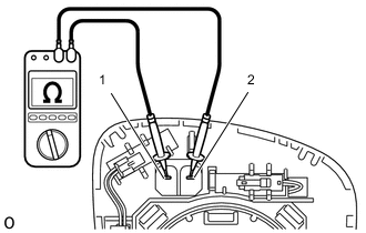
INSPECT OUTER MIRROR (for Driver Side)
-
for LHD
-
Remove the outer mirror LH Click here.
-
Measure the resistance according to the value(s) in the table below.
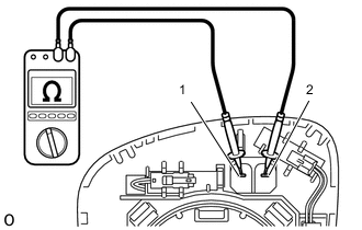
Standard resistance Tester Connection Condition Specified Condition 1 - 2 25°C (77°F) 3.6 to 4.8 Ω
-
-
for RHD
-
Remove the outer mirror RH Click here.
-
Measure the resistance according to the value(s) in the table below.
Standard resistance Tester Connection Condition Specified Condition 1 - 2 25°C (77°F) 3.6 to 4.8 Ω
-
OK
REPLACE OUTER MIRROR ACTUATOR ASSEMBLY (for Driver Side) Click here
NG
REPLACE OUTER MIRROR (for Driver Side) Click here
-
-
INSPECT OUTER REAR VIEW MIRROR ASSEMBLY (for Passenger Side)
-

for LHD:
-
Remove the outer rear view mirror RH Click here.
-
Measure the resistance according to the value(s) in the table below.
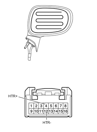
Standard resistance Tester Connection Condition Specified Condition 4 (HTR+) - 12 (HTR-) 25°C (77°F) 3.6 to 4.8 Ω -
Apply battery voltage and check the mirror heater operation.
OK Measurement Condition Specified Condition Battery positive (+) → Terminal 4 (HTR+)
Battery negative (-) → Terminal 12 (HTR-)
Mirror becomes warm Tech Tips
It will take a short time for the mirror to become warm.
-
-

for RHD:
-
Remove the outer rear view mirror LH Click here.
-
Measure the resistance according to the value(s) in the table below.
Standard resistance Tester Connection Condition Specified Condition 4 (HTR+) - 12 (HTR-) 25°C (77°F) 3.6 to 4.8 Ω -
Apply battery voltage and check the mirror heater operation.
OK Measurement Condition Specified Condition Battery positive (+) → Terminal 4 (HTR+)
Battery negative (-) → Terminal 12 (HTR-)
Mirror becomes warm Tech Tips
It will take a short time for the mirror to become warm.
-
OK
REPLACE FRONT DOOR ECU (for Passenger Side) Click here
NG
-
-
INSPECT OUTER MIRROR (for Passenger Side)
-
for LHD
-
Remove the outer mirror RH Click here.
-
Measure the resistance according to the value(s) in the table below.
Standard resistance Tester Connection Condition Specified Condition 1 - 2 25°C (77°F) 3.6 to 4.8 Ω
-
-
for RHD
-
Remove the outer mirror LH Click here.
-
Measure the resistance according to the value(s) in the table below.
Standard resistance Tester Connection Condition Specified Condition 1 - 2 25°C (77°F) 3.6 to 4.8 Ω
-
OK
REPLACE OUTER MIRROR ACTUATOR ASSEMBLY (for Passenger Side) Click here
NG
REPLACE OUTER MIRROR (for passenger Side) Click here
-