WINDOW DEFOGGER SYSTEM TERMINALS OF ECU
-
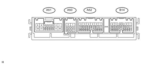
CHECK FRONT CONTROLLER
-
Disconnect the A50 and A52 front controller connectors.
-
Measure the resistance and voltage according to the value(s) in the table below.
Terminal No. (Symbols) Wiring Color Terminal Description Condition Specified Condition A52-1 (BATB) - A50-2 (E) P - W-B Power source Always 11 to 14 V A52-5 (ALTB) - A50-2 (E) L - W-B Power source Always 11 to 14 V A50-1 (FMB3) - A50-2 (E) LG - W-B Power source Always 11 to 14 V A50-2 (E) - Body ground W-B - Body ground Ground Always Below 1 Ω A50-5 (FMIG) - A50-2 (E) Y - W-B Ignition power supply Power switch ON (IG) 11 to 14 V Power switch OFF Below 1 V -
Reconnect the front controller connectors.
-
Measure the voltage according to the value(s) in the table below.
Terminal No. (Symbols) Wiring Color Terminal Description Condition Specified Condition A51-12 (RDEF) - A50-2 (E) W - W-B Defogger relay Power switch ON (IG)
Rear defogger switch ON
Below 1 V Power switch ON (IG)
Rear defogger switch OFF
11 to 14 V
-
-
CHECK AIR CONDITIONING AMPLIFIER Click here
-
CHECK MULTI-MEDIA MODULE RECEIVER ASSEMBLY Click here