REAR MILLIMETER WAVE RADAR SENSOR ADJUSTMENT
PROCEDURE
-
ADJUST REAR MILLIMETER WAVE RADAR SENSOR ASSEMBLY
Note
-
The rear millimeter wave radar sensor may or may not operate properly depending on the painted areas around the sensor. When replacing, applying paint to, or repairing the rear bumper cover, follow the procedures in the table below.
-
After the sensor is replaced or removed and installed, this adjustment is necessary.
No. Procedures 1 Check if there is any damage within 50 cm to the left and right of the center of the rear bumper.
-
If there is damage, go to the next step.
-
If there is no damage, go to step 7.
2 Remove the rear bumper cover. Check if there is damage on the rear reinforcement.
-
If there is damage, go to the next step.
-
If there is no damage, go to step 7.
3 Repair the rear body and go to the next step. 4 Check if the rear millimeter wave radar sensor assembly is damaged.
-
If there is damage, go to the next step.
-
If there is no damage, go to step 7.
5 Replace the rear millimeter wave radar sensor assembly and go to the next step. 6 Perform the rear millimeter wave radar sensor assembly vertical axis adjustment, and go to the next step. 7 Check if the rear bumper cover can be repaired.
-
If replacing the rear bumper cover, go to the next step.
-
If repairing the rear bumper cover, go to step 11.
8 Replace the rear bumper cover and go to the next step. 9 Check if it is necessary to perform color matching of the rear bumper.
-
If performing color matching, go to the next step.
-
If not performing color matching, go to step 15.
10 Perform color match painting and go to step 15. 11 Check if the rear bumper cover has any history of overcoat painting repairs.
-
If there is no repair history, go to the next step.
-
If there is repair history, go to step 13.
12 Perform overcoat painting and go to step 15. 13 Install the rear bumper cover and go to the next step. 14 Perform the rear millimeter wave radar sensor assembly check (wave dampening check).
-
If the tester measurement values are all less than 134, go to step 12.
-
If even one tester measurement value is 134 or more, go to step 8.
15 Install the rear bumper cover and go to the next step. 16 If the rear millimeter wave radar sensor assembly was replaced or removed, perform the sensor level axis adjustment. The adjustment is complete.
-
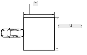
*1 Approximately 5 m (197 in.) *2 Approximately 6 m (236 in.) ADJUST VERTICAL AXIS OF REAR MILLIMETER WAVE RADAR SENSOR ASSEMBLY
-
Move the vehicle to a place with a level surface, and where there is a 5 m (197 in.) by 6 m (236 in.) area to the rear of the vehicle without large pieces of metal or reflective objects.
-
Unload the vehicle.
-
Adjust the pressure of the tires to the standard value.
-
Remove the rear bumper cover.
-
Place a level on top of the sensor.
-
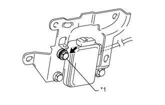
*1 Adjusting Bolt Using a socket wrench, adjust the vertical axis adjusting bolt so that the level's air bubble is at the center of the level.
-
Install the rear bumper cover.
Tech Tips
One rotation of the vertical axis adjusting bolt moves the sensor approximately 1°.
-
-
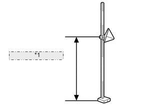
*1 540 +/-10 mm (21.3 +/-0.394 in.) ADJUST HORIZONTAL AXIS OF REAR MILLIMETER WAVE RADAR SENSOR ASSEMBLY
-
Set the reflector of SST (corner reflector) at a height of 540 +/-10 mm (21 +/-0.4 in.) from the ground (height of rear millimeter wave radar sensor assembly).
-
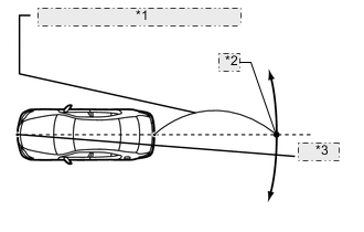
*1 2800 +/-20 mm (110 +/-0.787 in.) *2 Marking Point *3 String From the center of the front and back bumpers (center of the emblems), hang a weight with a pointed tip, and mark the front bumper center point and the rear bumper center point on the ground.
-
Make a line that connects the 2 center points, and extend the line approximately 2800 +/-20 mm (110 +/-0.787 in.) beyond the rear of the vehicle. Then mark that point on the ground.
Tech Tips
Secure the end of a string to the front bumper center point. Then hold the other end of the string approximately 2800 +/-20 mm (110 +/-0.787 in.) behind the vehicle, and move it to the left or right to align the string with the rear bumper center point to make a straight line.
-
Place SST (corner reflector) within 0 +/-10 mm (0 +/-0.394 in.) from the marking point made beyond the rear of the vehicle.
Note
Perform this procedure as accurately as possible.
-
Connect the intelligent tester to the DLC3 of the vehicle and turn the power switch ON (IG).
-
Turn off the taillights.
-
Enter the following menus: Body / Pre-Crash2 / Rear Beam Axis Adjustment. Then press NEXT.
Tech Tips
A beeping is heard for approximately one second.
-
After confirming the amount of deviation, move SST (corner reflector) 0.5 m (19.7 in.) to the left or right, and check that the left/right value changes. (However, a value above 6.3° will not be displayed.)
Note
If the value does not change, check the installation condition of the rear millimeter wave radar sensor, as it may be targeted at another object due to being misaligned. Also, check the surrounding area again, as the sensor may be targeting reflective objects near SST (corner reflector).
-
Return SST (corner reflector) to its original location, and check the amount of deviation.
Specified value Within 4.0° Tech Tips
When the amount of deviation exceeds the specified value, repair the vehicle body to the specified dimensions. The rear millimeter wave radar sensor cannot automatically adjust itself if the vehicle body is deformed.
-
Turn on the taillights.
Tech Tips
-
When the axis adjustment is completed, the buzzer sounds for 10 seconds and the left and right deviation amount display shows 0.0°.
-
If the buzzer does not sound, perform the axis adjustment again.
-
-
Press the "EXIT" button to finish the axis beam adjustment mode.
Tech Tips
After the axis beam adjustment is completed, if the adjustment mode is restarted, the same amount of deviation shown before performing the adjustment will be displayed. However, this is not a malfunction. The adjustment was completed at the point when the taillights were turned on and the amount of deviation was recorded as 0.0°. (The sensor has not been moved physically. It only has been calibrated and adjusted. Therefore, the same amount of deviation will be displayed every time.) Performing this procedure more than once is not necessary.
-
-
-
INSPECT REAR MILLIMETER WAVE RADAR SENSOR ASSEMBLY (WAVE DAMPENING CHECK)
Tech Tips
If the PCS indicator illuminates several times and the multi-information display displays "PCS not Available Now" regardless of rear bumper cover foreign matter (snow, dirt, etc.), remove the rear bumper cover and perform this inspection.
-
If all 4 intelligent tester measurement values is less than 26, replace the rear bumper cover (it may have a thick coat of paint).
-
If even one of the 4 intelligent tester measurement values are 26 or more, replace the rear millimeter wave radar sensor assembly.
-
*1 Approximately 5 m (197 in.) *2 Approximately 6 m (236 in.) Preparation
-
Move the vehicle to a place with a level surface, and where there is a 5 m (197 in.) by 6 m (236 in.) area to the rear of the vehicle without large pieces of metal or reflective objects.
-
Unload the vehicle.
-
Adjust the pressure of the tires to the standard value.
-
If the rear bumper is wet, wipe it dry.
-
Wipe off any foreign matter on the rear bumper.
-
-
Connect the intelligent tester to the DLC3 of the vehicle and turn the power switch ON (IG).
-
Enter the following menus: Body / Pre-Crash2 / Rear Radar Sensor Check.
-
*1 540 +/-10 mm (21.3 +/-0.394 in.) Set the reflector of SST (corner reflector) at a height of 540 +/-10 mm (21.3 +/-0.394 in.) from the ground (height of rear millimeter wave radar sensor assembly).
-
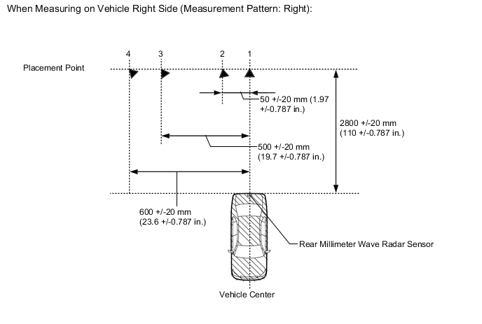
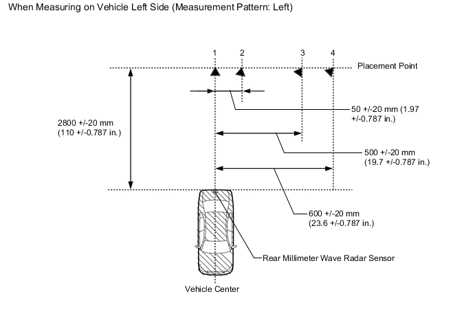
Set SST (corner reflector) at placement point 1 and follow the intelligent tester screens to read the measurement values of placement point 1, 2, 3 and 4.
Note
When placing SST (corner reflector), face the reflector toward the rear millimeter wave radar sensor assembly.
Tech Tips
Perform either the right or left side inspection.
-
At the screen "Welcome to the Rear Radar Sensor Check Utility", select NEXT.
-
At the screen "This RADAR transmits radio wave during adjustment", select NEXT.
-
At the screen "Confirm the following conditions", select NEXT.
-
At the screen "Select a measuring pattern", choose whether to move the reflector to the right or left side of the vehicle for the inspection, select NEXT.
-
At the screen "Please set up the target at position 1", select NEXT.
-
At the screen "Measured value of a position 1", the measurement for placement point 1 is displayed, and select NEXT.
-
At the screen "Please set up the target at position 2", select NEXT.
-
At the screen "Measured value of a position 2", the measurement for placement point 2 is displayed, and select NEXT.
-
At the screen "Please set up the target at position 3", select NEXT.
-
At the screen "Measured value of a position 3", the measurement for placement point 3 is displayed, and select NEXT.
-
At the screen "Please set up the target at position 4", select NEXT.
-
At the screen "Measured value of a position 4", the measurement for placement point 4 is displayed, and select NEXT.
-
At the screen "Rear Radar Sensor Check is complete", and select EXIT.
-