SPIRAL CABLE INSPECTION
PROCEDURE
-
INSPECT SPIRAL CABLE SUB-ASSEMBLY
-
Visually check for defects with the spiral cable sub-assembly removed from the vehicle.
-
The defects are as follows:
-
Scratches on the spiral cable sub-assembly
-
Small cracks the spiral cable sub-assembly
-
Dents on the spiral cable sub-assembly
-
Chips on the spiral cable sub-assembly
-
Cracks or other damage to the connector
OK No defects are found. Tech Tips
If any of the defects is found, replace the spiral cable sub-assembly with a new one.
-
-
-
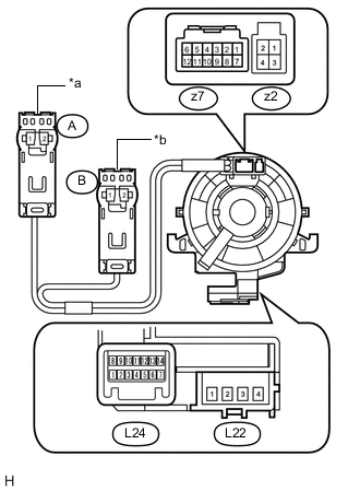
Text in Illustration *a Orange *b Black w/o Steering Heater:
Check the spiral cable sub-assembly.
Note
As the spiral cable sub-assembly may break, do not rotate the spiral cable more than the specified amount.
-
Set the spiral cable sub-assembly to the center position Click here.
-
Measure the resistance between each terminal of the spiral cable sub-assembly according to the table below.
-
After setting the spiral cable sub-assembly to the center position, rotate the spiral cable sub-assembly 2.5 times clockwise, and measure the resistance as shown. Then rotate the spiral cable sub-assembly 5 times counterclockwise, and measure the resistance as shown.
Standard Resistance Tester Connection Condition Specified Condition L22-1 - B2 Always Below 1 Ω L22-2 - B1 L22-3 - A1 L22-4 - A2 L24-1 - L23-3 L24-2 - z7-7 L24-2 - L23-4 L24-3 - z7-8 L24-4 - z7-9 L24-5 - z7-10 L24-6 - z7-11 L24-7 - z7-12 L24-8 - L23-2 L24-9 - z7-1 L24-10 - z7-2 L24-11 - z7-3 L24-12 - z7-4 L24-13 - z7-5 L24-14 - z7-6 If the value is not within the specified range, replace the spiral cable sub-assembly.
-
-
w/ Steering Heater:
Check the spiral cable sub-assembly.
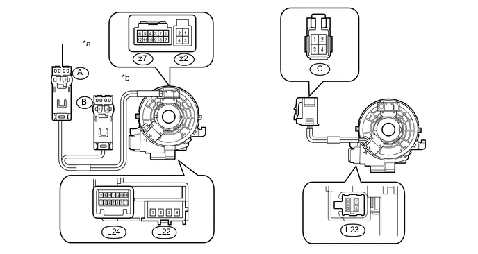
Text in Illustration *a Orange *b Black Note
As the spiral cable sub-assembly may break, do not rotate the spiral cable sub-assembly more than the specified amount.
-
Set the spiral cable sub-assembly to the center position Click here.
-
Measure the resistance between each terminal of the spiral cable sub-assembly according to the table below.
-
After setting the spiral cable sub-assembly to the center position, rotate the spiral cable sub-assembly 2.5 times clockwise, and measure the resistance as shown. Then rotate the spiral cable sub-assembly 5 times counterclockwise, and measure the resistance as shown.
Standard Resistance Tester Connection Condition Specified Condition L22-1 - B2 Always Below 1 Ω L22-2 - B1 L22-3 - A1 L22-4 - A2 L24-1 - L23-3 L24-2 - z7-7 L24-2 - L23-4 L24-3 - z7-8 L24-4 - z7-9 L24-5 - z7-10 L24-6 - z7-11 L24-7 - z7-12 L24-8 - L23-2 L24-9 - z7-1 L24-10 - z7-2 L24-11 - z7-3 L24-12 - z7-4 L24-13 - z7-5 L24-14 - z7-6 C-1 - L23-1 Below 3 Ω C-2 - L23-3 C-3 - L23-2 Less than 1 Ω C-4 - L23-4 If the value is not within the specified range, replace the spiral cable sub-assembly.
-
-