CAN COMMUNICATION SYSTEM(for RHD) Hybrid Vehicle Control ECU Communication Stop Mode
DESCRIPTION
| Detection Item | Symptom | Trouble Area |
|---|---|---|
| Hybrid Vehicle Control ECU Communication Stop Mode | Either condition is met:
|
|
WIRING DIAGRAM
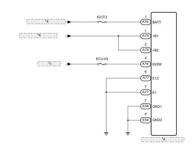
| *a | from Auxiliary Battery |
| *b | from ST CUT/IGCT2 Relay |
| *c | from IG2 Relay |
| *d | Hybrid Vehicle Control ECU |
CAUTION / NOTICE / HINT
Note
Inspect the fuses for circuits related to this system before performing the following inspection procedure.
PROCEDURE
-
CHECK HARNESS AND CONNECTOR (HYBRID VEHICLE CONTROL ECU - BATTERY AND BODY GROUND)
-
Disconnect the hybrid vehicle control ECU connectors.
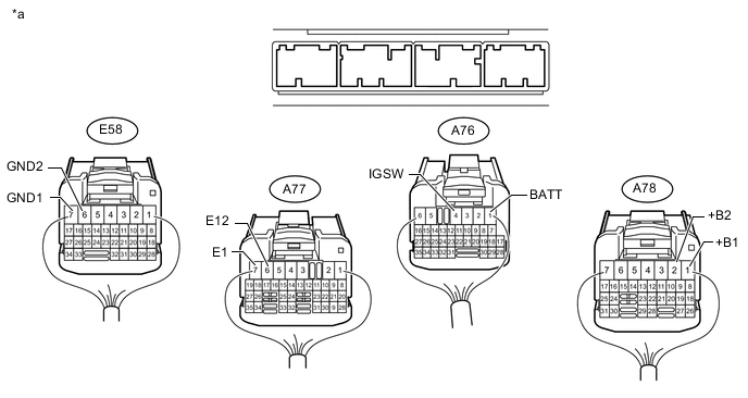
Text in Illustration *a Rear view of wire harness connector
(to Hybrid Vehicle Control ECU)
- - -
Measure the voltage according to the value(s) in the table below.
Standard Voltage Tester Connection Condition Specified Condition A76-1 (BATT) - Body ground Always 11 to 14 V A76-4 (IGSW) - Body ground Power switch on (IG) 11 to 14 V A78-1 (+B1) - Body ground Power switch on (IG) 11 to 14 V A78-2 (+B2) - Body ground Power switch on (IG) 11 to 14 V -
Measure the resistance according to the value(s) in the table below.
Standard Resistance Tester Connection Condition Specified Condition A77-7 (E1) - Body ground Always Below 1 Ω A77-6 (E12) - Body ground Always Below 1 Ω E58-7 (GND1) - Body ground Always Below 1 Ω E58-6 (GND2) - Body ground Always Below 1 Ω
OK 
REPLACE HYBRID VEHICLE CONTROL ECU Click here
NG
REPAIR OR REPLACE HARNESS OR CONNECTOR
-