CAN COMMUNICATION SYSTEM(for LHD) Short to GND in CAN Bus Line
DESCRIPTION
There may be a short circuit between the CAN bus lines and GND when the resistance between terminals 6 (CANH) and 4 (CG) or terminals 14 (CANL) and 4 (CG) of the DLC3 is below 200 Ω.
| Symptom | Trouble Area |
|---|---|
| The resistance between terminals 6 (CANH) and 4 (CG) or terminals 14 (CANL) and 4 (CG) of the DLC3 is below 200 Ω. |
|
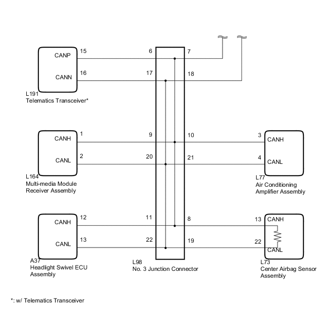
*: w/ Telematics Transceiver
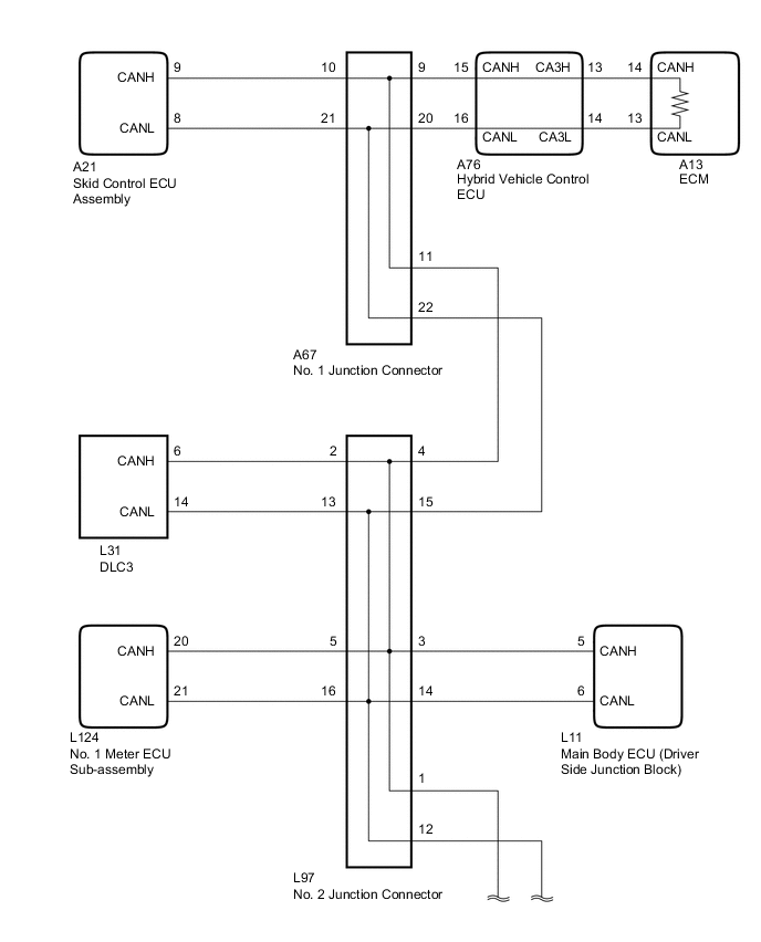
WIRING DIAGRAM
CAUTION / NOTICE / HINT
Note
The vehicle is equipped with an SRS (Supplemental Restraint System) which includes components such as airbags. Before servicing (including removal or installation of parts), be sure to read the Precaution in the SRS Click here.
Tech Tips
Operating the power switch, any switches or any doors triggers related ECU and sensor communication with the CAN, which causes resistance variation.
PROCEDURE
-
PRECAUTION
Note
After turning the power switch off, waiting time may be required before disconnecting the cable from the auxiliary battery terminal. Therefore, make sure to read the disconnecting the cable from the auxiliary battery terminal notice before proceeding with work Click here.
NEXT 
-
DISCONNECT CABLE FROM NEGATIVE AUXILIARY BATTERY TERMINAL
-
Disconnect the cable from the negative (-) auxiliary battery terminal before measuring the resistances of the CAN main wire and the CAN branch wire.
CAUTION:
Wait at least 90 seconds after disconnecting the cable from the negative (-) auxiliary battery terminal to disable the SRS system.
Note
When disconnecting the cable, some systems need to be initialized after the cable is reconnected Click here.
NEXT
-
-
CHECK FOR SHORT TO GND IN CAN BUS WIRE (NO. 2 JUNCTION CONNECTOR - DLC3)
-
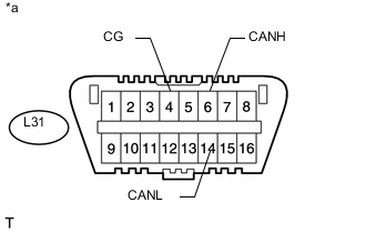
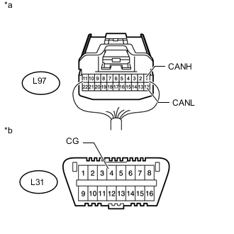
Text in Illustration *a Front view of DLC3 Disconnect the L97 No. 2 junction connector.
-
Measure the resistance according to the value(s) in the table below.
Standard Resistance Tester Connection Switch Condition Specified Condition L31-6 (CANH) - L31-4 (CG) Power switch off 200 Ω or higher L31-14 (CANL) - L31-4 (CG) Power switch off 200 Ω or higher
NG 
REPAIR OR REPLACE CAN BRANCH WIRE CONNECTED TO DLC3 (CANH, CANL)
OK
-
-
CONNECT CONNECTOR
-
Reconnect the L97 No. 2 junction connector.
NEXT
-
-
CHECK FOR SHORT TO GND IN CAN BUS WIRE (NO. 1 JUNCTION CONNECTOR SIDE)
-
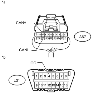
Text in Illustration *a Front view of DLC3 Disconnect the A67 No. 1 junction connector.
-
Measure the resistance according to the value(s) in the table below.
Standard Resistance Tester Connection Switch Condition Specified Condition L31-6 (CANH) - L31-4 (CG) Power switch off 200 Ω or higher L31-14 (CANL) - L31-4 (CG) Power switch off 200 Ω or higher
NG 
CONNECT CONNECTOR Click here
OK
-
-
CHECK FOR SHORT TO GND IN CAN BUS WIRE (NO. 1 JUNCTION CONNECTOR - SKID CONTROL ECU ASSEMBLY)
-
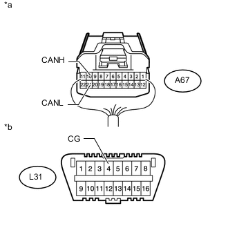
Text in Illustration *a Rear view of wire harness connector
(to No. 1 Junction Connector)
*b Front view of DLC3 Measure the resistance according to the value(s) in the table below.
Standard Resistance Tester Connection Switch Condition Specified Condition A67-10 (CANH) - L31-4 (CG) Power switch off 200 Ω or higher A67-21 (CANL) - L31-4 (CG) Power switch off 200 Ω or higher
NG
CONNECT CONNECTOR Click here
OK
-
-
CHECK FOR SHORT TO GND IN CAN BUS WIRE (NO. 1 JUNCTION CONNECTOR - ECM)
-
Text in Illustration *a Rear view of wire harness connector
(to No. 1 Junction Connector)
*b Front view of DLC3 Measure the resistance according to the value(s) in the table below.
Standard Resistance Tester Connection Switch Condition Specified Condition A67-9 (CANH) - L31-4 (CG) Power switch off 200 Ω or higher A67-20 (CANL) - L31-4 (CG) Power switch off 200 Ω or higher
OK
REPLACE NO. 1 JUNCTION CONNECTOR
NG
CONNECT CONNECTOR Click here
-
-
CONNECT CONNECTOR
-
Reconnect the A67 No. 1 junction connector.
NEXT
-
-
CHECK FOR SHORT TO GND IN CAN BUS WIRE (SKID CONTROL ECU ASSEMBLY)
-
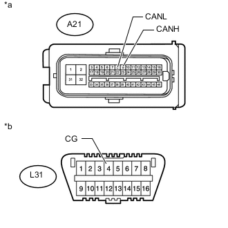
Text in Illustration *a Front view of wire harness connector
(to Skid Control ECU Assembly)
*b Front view of DLC3 Disconnect the skid control ECU assembly connector.
-
Measure the resistance according to the value(s) in the table below.
Standard Resistance Tester Connection Switch Condition Specified Condition A21-9 (CANH) - L31-4 (CG) Power switch off 200 Ω or higher A21-8 (CANL) - L31-4 (CG) Power switch off 200 Ω or higher
OK
REPLACE SKID CONTROL ECU ASSEMBLY Click here
NG
REPAIR OR REPLACE CAN BRANCH WIRE CONNECTED TO SKID CONTROL ECU ASSEMBLY (CANH, CANL)
-
-
CONNECT CONNECTOR
-
Reconnect the A67 No. 1 junction connector.
NEXT
-
-
CHECK FOR SHORT TO GND IN CAN BUS WIRE (ECM)
-
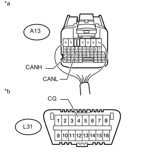
Text in Illustration *a Rear view of wire harness connector
(to ECM)
*b Front view of DLC3 Disconnect the ECM connector.
-
Measure the resistance according to the value(s) in the table below.
Standard Resistance Tester Connection Switch Condition Specified Condition A13-14 (CANH) - L31-4 (CG) Power switch off 200 Ω or higher A13-13 (CANL) - L31-4 (CG) Power switch off 200 Ω or higher
OK
REPLACE ECM Click here
NG
-
-
CONNECT CONNECTOR
-
Reconnect the A13 ECM connector.
NEXT
-
-
CHECK FOR SHORT TO GND IN CAN BUS WIRE (HYBRID VEHICLE CONTROL ECU - ECM)
-
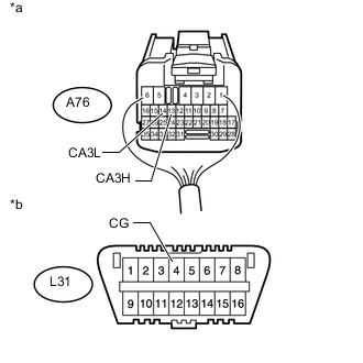
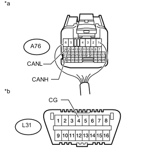
Text in Illustration *a Rear view of wire harness connector
(to Hybrid Vehicle Control ECU)
*b Front view of DLC3 Disconnect the hybrid vehicle control ECU connector.
-
Measure the resistance according to the value(s) in the table below.
Standard Resistance Tester Connection Switch Condition Specified Condition A76-13 (CA3H) - L31-4 (CG) Power switch off 200 Ω or higher A76-14 (CA3L) - L31-4 (CG) Power switch off 200 Ω or higher
NG
REPAIR OR REPLACE CAN MAIN WIRE OR CONNECTOR (HYBRID VEHICLE CONTROL ECU - ECM)
OK
-
-
CHECK FOR SHORT TO GND IN CAN BUS WIRE (HYBRID VEHICLE CONTROL ECU - NO. 1 JUNCTION CONNECTOR)
-
Text in Illustration *a Rear view of wire harness connector
(to Hybrid Vehicle Control ECU)
*b Front view of DLC3 Measure the resistance according to the value(s) in the table below.
Standard Resistance Tester Connection Switch Condition Specified Condition A76-15 (CANH) - L31-4 (CG) Power switch off 200 Ω or higher A76-16 (CANL) - L31-4 (CG) Power switch off 200 Ω or higher
OK
REPLACE HYBRID VEHICLE CONTROL ECU Click here
NG
REPAIR OR REPLACE CAN MAIN WIRE OR CONNECTOR (HYBRID VEHICLE CONTROL ECU - NO. 1 JUNCTION CONNECTOR)
-
-
CONNECT CONNECTOR
-
Reconnect the A67 No. 1 junction connector.
NEXT
-
-
CHECK FOR SHORT TO GND IN CAN BUS WIRE (NO. 2 JUNCTION CONNECTOR - NO. 1 JUNCTION CONNECTOR)
-
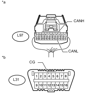
Text in Illustration *a Rear view of wire harness connector
(to No. 2 Junction Connector)
*b Front view of DLC3 Disconnect the No. 2 junction connector.
-
Measure the resistance according to the value(s) in the table below.
Standard Resistance Tester Connection Switch Condition Specified Condition L97-4 (CANH) - L31-4 (CG) Power switch off 200 Ω or higher L97-15 (CANL) - L31-4 (CG) Power switch off 200 Ω or higher
NG
REPAIR OR REPLACE CAN MAIN WIRE OR CONNECTOR (NO. 2 JUNCTION CONNECTOR - NO. 1 JUNCTION CONNECTOR)
OK
-
-
CONNECT CONNECTOR
-
Reconnect the L97 No. 2 junction connector.
NEXT
-
-
CHECK FOR SHORT TO GND IN CAN BUS WIRE (NO. 3 JUNCTION CONNECTOR SIDE)
-
Text in Illustration *a Front view of DLC3 Disconnect the L98 No. 3 junction connector.
-
Measure the resistance according to the value(s) in the table below.
Standard Resistance Tester Connection Switch Condition Specified Condition L31-6 (CANH) - L31-4 (CG) Power switch off 200 Ω or higher L31-14 (CANL) - L31-4 (CG) Power switch off 200 Ω or higher
NG
CONNECT CONNECTOR Click here
OK
-
-
CHECK FOR SHORT TO GND IN CAN BUS WIRE (NO. 3 JUNCTION CONNECTOR - TELEMATICS TRANSCEIVER)
Note
For vehicles without a telematics transceiver, go to "Check for Short in CAN Bus Wires (No. 3 Junction Connector - Multi-media Module Receiver Assembly)".
-
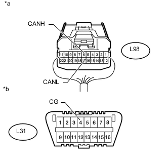
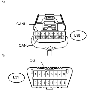
Text in Illustration *a Rear view of wire harness connector
(to No. 3 Junction Connector)
*b Front view of DLC3 Measure the resistance according to the value(s) in the table below.
Standard Resistance Tester Connection Switch Condition Specified Condition L98-6 (CANH) - L31-4 (CG) Power switch off 200 Ω or higher L98-17 (CANL) - L31-4 (CG) Power switch off 200 Ω or higher
NG
CONNECT CONNECTOR Click here
OK
-
-
CHECK FOR SHORT TO GND IN CAN BUS WIRE (NO. 3 JUNCTION CONNECTOR - MULTI-MEDIA MODULE RECEIVER ASSEMBLY)
-
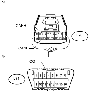
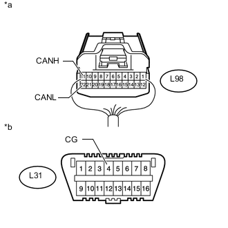
Text in Illustration *a Rear view of wire harness connector
(to No. 3 Junction Connector)
*b Front view of DLC3 Measure the resistance according to the value(s) in the table below.
Standard Resistance Tester Connection Switch Condition Specified Condition L98-9 (CANH) - L31-4 (CG) Power switch off 200 Ω or higher L98-20 (CANL) - L31-4 (CG) Power switch off 200 Ω or higher
NG
CONNECT CONNECTOR Click here
OK
-
-
CHECK FOR SHORT TO GND IN CAN BUS WIRE (NO. 3 JUNCTION CONNECTOR - AIR CONDITIONING AMPLIFIER ASSEMBLY)
-
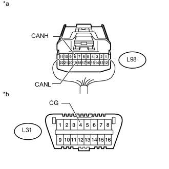
Text in Illustration *a Rear view of wire harness connector
(to No. 3 Junction Connector)
*b Front view of DLC3 Measure the resistance according to the value(s) in the table below.
Standard Resistance Tester Connection Switch Condition Specified Condition L98-10 (CANH) - L31-4 (CG) Power switch off 200 Ω or higher L98-21 (CANL) - L31-4 (CG) Power switch off 200 Ω or higher
NG
CONNECT CONNECTOR Click here
OK
-
-
CHECK FOR SHORT TO GND IN CAN BUS WIRE (NO. 3 JUNCTION CONNECTOR - HEADLIGHT SWIVEL ECU ASSEMBLY)
-
Text in Illustration *a Rear view of wire harness connector
(to No. 3 Junction Connector)
*b Front view of DLC3 Measure the resistance according to the value(s) in the table below.
Standard Resistance Tester Connection Switch Condition Specified Condition L98-11 (CANH) - L31-4 (CG) Power switch off 200 Ω or higher L98-22 (CANL) - L31-4 (CG) Power switch off 200 Ω or higher
NG
CONNECT CONNECTOR Click here
OK
-
-
CHECK FOR SHORT TO GND IN CAN BUS WIRE (NO. 3 JUNCTION CONNECTOR - CENTER AIRBAG SENSOR ASSEMBLY)
-
Text in Illustration *a Rear view of wire harness connector
(to No. 3 Junction Connector)
*b Front view of DLC3 Measure the resistance according to the value(s) in the table below.
Standard Resistance Tester Connection Switch Condition Specified Condition L98-8 (CANH) - L31-4 (CG) Power switch off 200 Ω or higher L98-19 (CANL) - L31-4 (CG) Power switch off 200 Ω or higher
OK
REPLACE NO. 3 JUNCTION CONNECTOR
NG
CONNECT CONNECTOR Click here
-
-
CONNECT CONNECTOR
-
Reconnect the L98 No. 3 junction connector.
NEXT
-
-
CHECK FOR SHORT TO GND IN CAN BUS WIRE (TELEMATICS TRANSCEIVER)
-
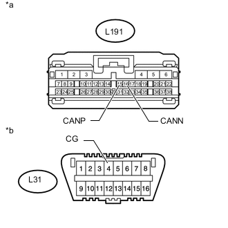
Text in Illustration *a Front view of wire harness connector
(to Telematics Transceiver)
*b Front view of DLC3 Disconnect the telematics transceiver connector.
-
Measure the resistance according to the value(s) in the table below.
Standard Resistance Tester Connection Switch Condition Specified Condition L191-15 (CANP) - L31-4 (CG) Power switch off 200 Ω or higher L191-16 (CANN) - L31-4 (CG) Power switch off 200 Ω or higher
OK
REPLACE TELEMATICS TRANSCEIVER Click here
NG
REPAIR OR REPLACE CAN BRANCH WIRE CONNECTED TO TELEMATICS TRANSCEIVER (CANP, CANN)
-
-
CONNECT CONNECTOR
-
Reconnect the L98 No. 3 junction connector.
NEXT
-
-
CHECK FOR SHORT TO GND IN CAN BUS WIRE (MULTI-MEDIA MODULE RECEIVER ASSEMBLY)
-
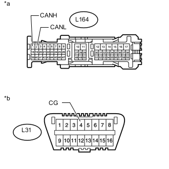
Text in Illustration *a Front view of wire harness connector
(to Multi-media Module Receiver Assembly)
*b Front view of DLC3 Disconnect the multi-media module receiver assembly connector.
-
Measure the resistance according to the value(s) in the table below.
Standard Resistance Tester Connection Switch Condition Specified Condition L164-1 (CANH) - L31-4 (CG) Power switch off 200 Ω or higher L164-2 (CANL) - L31-4 (CG) Power switch off 200 Ω or higher
OK
REPLACE MULTI-MEDIA MODULE RECEIVER ASSEMBLY Click here
NG
REPAIR OR REPLACE CAN BRANCH WIRE CONNECTED TO MULTI-MEDIA MODULE RECEIVER ASSEMBLY (CANH, CANL)
-
-
CONNECT CONNECTOR
-
Reconnect the L98 No. 3 junction connector.
NEXT
-
-
CHECK FOR SHORT TO GND IN CAN BUS WIRE (AIR CONDITIONING AMPLIFIER ASSEMBLY)
-
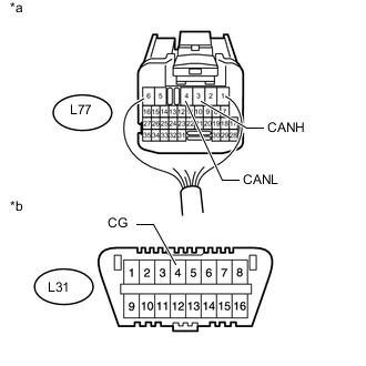
Text in Illustration *a Rear view of wire harness connector
(to Air Conditioning Amplifier Assembly)
*b Front view of DLC3 Disconnect the air conditioning amplifier assembly connector.
-
Measure the resistance according to the value(s) in the table below.
Standard Resistance Tester Connection Switch Condition Specified Condition L77-3 (CANH) - L31-4 (CG) Power switch off 200 Ω or higher L77-4 (CANL) - L31-4 (CG) Power switch off 200 Ω or higher
OK
REPLACE AIR CONDITIONING AMPLIFIER ASSEMBLY Click here
NG
REPAIR OR REPLACE CAN BRANCH WIRE CONNECTED TO AIR CONDITIONING AMPLIFIER ASSEMBLY (CANH, CANL)
-
-
CONNECT CONNECTOR
-
Reconnect the L98 No. 3 junction connector.
NEXT
-
-
CHECK FOR SHORT TO GND IN CAN BUS WIRE (HEADLIGHT SWIVEL ECU ASSEMBLY)
-
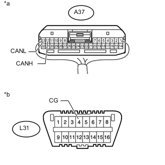
Text in Illustration *a Rear view of wire harness connector
(to Headlight Swivel ECU Assembly)
*b Front view of DLC3 Disconnect the headlight swivel ECU assembly connector.
-
Measure the resistance according to the value(s) in the table below.
Standard Resistance Tester Connection Switch Condition Specified Condition A37-12 (CANH) - L31-4 (CG) Power switch off 200 Ω or higher A37-13 (CANL) - L31-4 (CG) Power switch off 200 Ω or higher
OK
REPLACE HEADLIGHT SWIVEL ECU ASSEMBLY Click here
NG
REPAIR OR REPLACE CAN BRANCH WIRE CONNECTED TO HEADLIGHT SWIVEL ECU ASSEMBLY (CANH, CANL)
-
-
CONNECT CONNECTOR
-
Reconnect the L98 No. 3 junction connector.
NEXT
-
-
CHECK FOR SHORT TO GND IN CAN BUS WIRE (CENTER AIRBAG SENSOR ASSEMBLY)
-
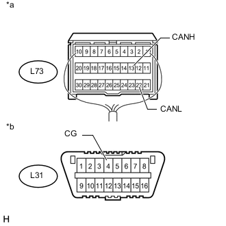
Text in Illustration *a Rear view of wire harness connector
(to Center Airbag Sensor Assembly)
*b Front view of DLC3 Disconnect the center airbag sensor assembly connector.
-
Measure the resistance according to the value(s) in the table below.
Standard Resistance Tester Connection Switch Condition Specified Condition L73-13 (CANH) - L31-4 (CG) Power switch off 200 Ω or higher L73-22 (CANL) - L31-4 (CG) Power switch off 200 Ω or higher
OK
REPLACE CENTER AIRBAG SENSOR ASSEMBLY Click here
NG
REPAIR OR REPLACE CAN MAIN WIRE CONNECTED TO CENTER AIRBAG SENSOR ASSEMBLY (CANH, CANL)
-
-
CONNECT CONNECTOR
-
Reconnect the L98 No. 3 junction connector.
NEXT
-
-
CHECK FOR SHORT TO GND IN CAN BUS WIRE (NO. 2 JUNCTION CONNECTOR - NO. 3 JUNCTION CONNECTOR)
-
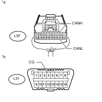
Text in Illustration *a Rear view of wire harness connector
(to No. 2 Junction Connector)
*b Front view of DLC3 Disconnect the No. 2 junction connector.
-
Measure the resistance according to the value(s) in the table below.
Standard Resistance Tester Connection Switch Condition Specified Condition L97-1 (CANH) - L31-4 (CG) Power switch off 200 Ω or higher L97-12 (CANL) - L31-4 (CG) Power switch off 200 Ω or higher
NG
REPAIR OR REPLACE CAN MAIN WIRE OR CONNECTOR (NO. 2 JUNCTION CONNECTOR - NO. 3 JUNCTION CONNECTOR)
OK
-
-
CHECK FOR SHORT TO GND IN CAN BUS WIRE (NO. 2 JUNCTION CONNECTOR - MAIN BODY ECU)
-
Text in Illustration *a Rear view of wire harness connector
(to No. 2 Junction Connector)
*b Front view of DLC3 Measure the resistance according to the value(s) in the table below.
Standard Resistance Tester Connection Switch Condition Specified Condition L97-3 (CANH) - L31-4 (CG) Power switch off 200 Ω or higher L97-14 (CANL) - L31-4 (CG) Power switch off 200 Ω or higher
NG
CONNECT CONNECTOR Click here
OK
-
-
CHECK FOR SHORT TO GND IN CAN BUS WIRE (NO. 2 JUNCTION CONNECTOR - NO. 1 METER ECU SUB-ASSEMBLY)
-
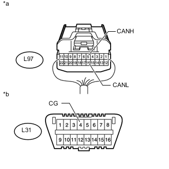
Text in Illustration *a Rear view of wire harness connector
(to No. 2 Junction Connector)
*b Front view of DLC3 Measure the resistance according to the value(s) in the table below.
Standard Resistance Tester Connection Switch Condition Specified Condition L97-5 (CANH) - L31-4 (CG) Power switch off 200 Ω or higher L97-16 (CANL) - L31-4 (CG) Power switch off 200 Ω or higher
OK
REPLACE NO. 2 JUNCTION CONNECTOR
NG
CONNECT CONNECTOR Click here
-
-
CONNECT CONNECTOR
-
Reconnect the L97 No. 2 junction connector.
NEXT
-
-
CHECK FOR SHORT TO GND IN CAN BUS WIRE (MAIN BODY ECU)
-
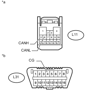
Text in Illustration *a Front view of wire harness connector
(to Main Body ECU [Driver Side Junction Block])
*b Front view of DLC3 Disconnect the main body ECU (driver side junction block) connector.
-
Measure the resistance according to the value(s) in the table below.
Standard Resistance Tester Connection Switch Condition Specified Condition L11-5 (CANH) - L31-4 (CG) Power switch off 200 Ω or higher L11-6 (CANL) - L31-4 (CG) Power switch off 200 Ω or higher
OK
REPLACE MAIN BODY ECU (DRIVER SIDE JUNCTION BLOCK)
NG
REPAIR OR REPLACE CAN BRANCH WIRE CONNECTED TO MAIN BODY ECU (CANH, CANL)
-
-
CONNECT CONNECTOR
-
Reconnect the L97 No. 2 junction connector.
NEXT
-
-
CHECK FOR SHORT TO GND IN CAN BUS WIRE (NO. 1 METER ECU SUB-ASSEMBLY)
-
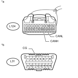
Text in Illustration *a Front view of wire harness connector
(to No. 1 Meter ECU Sub-assembly)
*b Front view of DLC3 Disconnect the No. 1 meter ECU sub-assembly connector.
-
Measure the resistance according to the value(s) in the table below.
Standard Resistance Tester Connection Switch Condition Specified Condition L124-20 (CANH) - L31-4 (CG) Power switch off 200 Ω or higher L124-21 (CANL) - L31-4 (CG) Power switch off 200 Ω or higher
OK
REPLACE NO. 1 METER ECU SUB-ASSEMBLY Click here
NG
REPAIR OR REPLACE CAN BRANCH WIRE CONNECTED TO NO. 1 METER ECU SUB-ASSEMBLY (CANH, CANL)
-