CAN COMMUNICATION SYSTEM(for LHD) TERMINALS OF ECU
Tech Tips
Operating the power switch, any switches or any doors triggers related ECU and sensor communication with the CAN, which causes resistance variation.
-
DISCONNECT CABLE FROM NEGATIVE AUXILIARY BATTERY TERMINAL
-
Disconnect the cable from the negative (-) auxiliary battery terminal before measuring the resistances of the CAN main wire and CAN branch wire.
CAUTION:
Wait at least 90 seconds after disconnecting the cable from the negative (-) auxiliary battery terminal to disable the SRS system.
Note
-
Before measuring the resistance, leave the vehicle for at least 1 minute and do not operate the power switch, any switches or any doors. If doors need to be opened in order to check connectors, open the doors and leave them open.
-
After turning the power switch off, waiting time may be required before disconnecting the cable from the negative (-) auxiliary battery terminal. Therefore, make sure to read the disconnecting the cable from the negative (-) auxiliary battery terminal notices before proceeding with work Click here.
-
When disconnecting the cable, some systems need to be initialized after the cable is reconnected Click here.
-
-
-
JUNCTION CONNECTOR
-
NO. 1 JUNCTION CONNECTOR
Text in Illustration *a Rear view of wire harness connector
(to No. 1 Junction Connector)
*b for No. 2 Junction Connector [Steering Bus] *c for Skid Control ECU Assembly [Steering Bus] *d for ECM (w/o Active Stabilizer Suspension System) *e for Driving Support ECU Assembly (w/ Pre-crash Safety System) *f for Front Active Stabilizer Control ECU Assembly (w/ Active Stabilizer Suspension System) *g for Hybrid Vehicle Control ECU *h for Skid control ECU assembly [V Bus] *i for No. 2 Junction Connector [V Bus] - - No. 1 Junction Connector Wiring Color Connect to A67-1 (CANH) B No. 2 junction connector [Steering bus] A67-12 (CANL) W A67-2 (CANH) R Skid control ECU assembly [Steering bus] A67-13 (CANL) G A67-3 (CANH) Y ECM*1 A67-14 (CANL) L A67-4 (CANH) B Driving support ECU assembly*2 A67-15 (CANL) W A67-5 (CANH) R Front active stabilizer control ECU assembly*3 A67-16 (CANL) G A67-9 (CANH) Y Hybrid vehicle control ECU A67-20 (CANL) L A67-10 (CANH) B Skid control ECU assembly [V bus] A67-21 (CANL) W A67-11 (CANH) R No. 2 junction connector [V bus] A67-22 (CANL) G
-
*1: w/o Active Stabilizer Suspension System
-
*2: w/ Pre-crash Safety System
-
*3: w/ Active Stabilizer Suspension System
-
-
NO. 2 JUNCTION CONNECTOR
Text in Illustration *a Rear view of wire harness connector
(to No. 2 Junction Connector)
*b for No. 3 Junction Connector *c for DLC3 *d for Main Body ECU (Driver Side Junction Block) *e for No. 1 Junction Connector [V Bus] *f for No. 1 Meter ECU Sub-assembly *g for Steering Angle Sensor *h for Yaw Rate Sensor *i for No. 4 Junction Connector *j for No. 1 Junction Connector [Steering Bus] No. 2 Junction Connector Wiring Color Connect to L97-1 (CANH) R No. 3 junction connector L97-12 (CANL) G L97-2 (CANH) R DLC3 L97-13 (CANL) G L97-3 (CANH) R Main body ECU (driver side junction block) L97-14 (CANL) G L97-4 (CANH) R No. 1 junction connector [V bus] L97-15 (CANL) G L97-5 (CANH) R No. 1 meter ECU sub-assembly L97-16 (CANL) G L97-8 (CANH) R Steering angle sensor L97-19 (CANL) W L97-9 (CANH) B Yaw rate sensor L97-20 (CANL) W L97-10 (CANH) B No. 4 junction connector L97-21 (CANL) W L97-11 (CANH) B No. 1 junction connector [Steering bus] L97-22 (CANL) W -
NO. 3 JUNCTION CONNECTOR
Text in Illustration *a Rear view of wire harness connector
(to No. 3 Junction Connector)
*b for Telematics Transceiver (w/ Telematics Transceiver) *c for No. 2 Junction Connector *d for Center Airbag Sensor Assembly *e for Multi-media Module Receiver Assembly *f for Air Conditioning Amplifier Assembly *g for Headlight Swivel ECU Assembly - - No. 3 Junction Connector Wiring Color Connect to L98-6 (CANH) R Telematics transceiver* L98-17 (CANL) G L98-7 (CANH) R No. 2 junction connector L98-18 (CANL) G L98-8 (CANH) R Center airbag sensor assembly L98-19 (CANL) G L98-9 (CANH) R Multi-media module receiver assembly L98-20 (CANL) G L98-10 (CANH) R Air conditioning amplifier assembly L98-21 (CANL) G L98-11 (CANH) R Headlight swivel ECU assembly L98-22 (CANL) G *: w/ Telematics Transceiver
-
NO. 4 JUNCTION CONNECTOR
Text in Illustration *a Rear view of wire harness connector
(to No. 4 Junction Connector)
*b for No. 5 Junction Connector *c for No. 2 Junction Connector *d for Seat Belt Control ECU (w/ Pre-crash Safety System) *e for Rear Active Stabilizer Control ECU Assembly [Steering Bus] (w/ Active Stabilizer Suspension System) *f for Blind Spot Monitor Sensor LH (w/ Blind Spot Monitor System) *g for Rear Active Stabilizer Control ECU Assembly [Braking and Driving Bus] (w/ Active Stabilizer Suspension System) *h for Parking Brake ECU Assembly *i for No. 6 Junction Connector - - No. 4 Junction Connector Wiring Color Connect to S58-1 (CANH) B No. 5 junction connector S58-12 (CANL) W S58-2 (CANH) B No. 2 junction connector S58-13 (CANL) W S58-3 (CANH) B Seat belt control ECU*1 S58-14 (CANL) W S58-4 (CANH) B Rear active stabilizer control ECU assembly [Steering Bus]*2 S58-15 (CANL) W S58-8 (CANH) Y Blind spot monitor sensor LH*3 S58-19 (CANL) B S58-9 (CANH) Y Rear active stabilizer control ECU assembly [Braking and Driving Bus]*2 S58-20 (CANL) L S58-10 (CANH) B Parking brake ECU assembly S58-21 (CANL) W S58-11 (CANH) B No. 6 junction connector S58-22 (CANL) W
-
*1: w/ Pre-crash Safety System
-
*2: w/ Active Stabilizer Suspension System
-
*3: w/ Blind Spot Monitor System
-
-
NO. 5 JUNCTION CONNECTOR
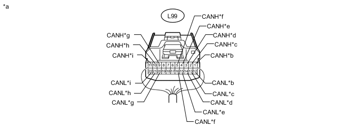
Text in Illustration *a Rear view of wire harness connector
(to No. 5 Junction Connector)
*b for Suspension Control ECU *c for Network Gateway ECU [Steering Bus] (w/ Pre-crash Intelligent Headrest) *d for No. 4 Junction Connector *e for Power Steering ECU Assembly *f for Steering Control ECU *g
-
for Active Headrest Control ECU RH (Front Seat Headrest Assembly RH) (w/ Pre-crash Intelligent Headrest [for 5- Passenger with Ottoman])
-
for No. 16 Junction Connector (w/ Pre-crash Intelligent Headrest [except 5- Passenger with Ottoman])
*h for Active headrest control ECU LH (front seat headrest assembly LH) (w/ Pre-crash Intelligent Headrest) *i for Network Gateway ECU [WIL Bus] (w/ Pre-crash Intelligent Headrest) - - No. 5 Junction Connector Wiring Color Connect to L99-1 (CANH) B Suspension control ECU L99-12 (CANL) W L99-2 (CANH) B Network gateway ECU [Steering Bus]*1 L99-13 (CANL) W L99-3 (CANH) B No. 4 junction connector L99-14 (CANL) W L99-4 (CANH) B Power steering ECU assembly L99-15 (CANL) W L99-5 (CANH) B Steering control ECU L99-16 (CANL) W L99-9 (CANH) R
-
Active headrest control ECU RH (front seat headrest assembly RH)*2
-
No. 16 junction connector*3
L99-20 (CANL) G L99-10 (CANH) R Active headrest control ECU LH (front seat headrest assembly LH)*1 L99-21 (CANL) G L99-11 (CANH) B Network gateway ECU [WIL Bus]*1 L99-22 (CANL) W
-
*1: w/ Pre-crash Intelligent Headrest
-
*2: w/ Pre-crash Intelligent Headrest (for 5-Passenger with Ottoman)
-
*3: w/ Pre-crash Intelligent Headrest (except 5-Passenger with Ottoman)
-
-
NO. 6 JUNCTION CONNECTOR
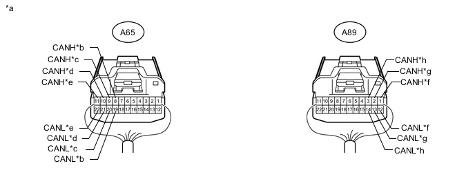
Text in Illustration *a Rear view of wire harness connector
(to No. 6 Junction Connector)
*b for Hybrid Vehicle Control ECU *c for Skid Control ECU Assembly *d for ECM *e for Driving Support ECU Assembly (w/ Pre-crash Safety System) *f for Front Active Stabilizer Control ECU Assembly (w/ Active Stabilizer Suspension System) *g for No. 7 Junction Connector *h for No. 4 Junction Connector No. 6 Junction Connector Wiring Color Connect to A65-8 (CANH) B Hybrid vehicle control ECU A65-19 (CANL) W A65-9 (CANH) Y Skid control ECU assembly A65-20 (CANL) L A65-10 (CANH) R ECM A65-21 (CANL) G A65-11 (CANH) B Driving support ECU assembly*1 A65-22 (CANL) W A89-1 (CANH) Y Front active stabilizer control ECU assembly*2 A89-12 (CANL) L A89-2 (CANH) R No. 7 junction connector A89-13 (CANL) G A89-3 (CANH) B No. 4 junction connector A89-14 (CANL) W
-
*1: w/ Pre-crash Safety System
-
*2: w/ Active Stabilizer Suspension System
-
-
NO. 7 JUNCTION CONNECTOR
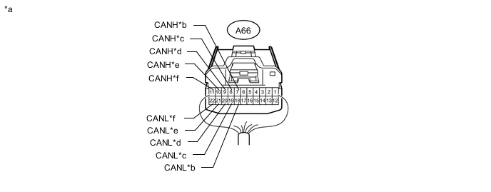
Text in Illustration *a Rear view of wire harness connector
(to No. 7 Junction Connector)
*b for Clearance Warning ECU Assembly *c for No. 6 Junction Connector *d for Suspension Control ECU *e for Steering Control ECU *f for Power Steering ECU Assembly No. 7 Junction Connector Wiring Color Connect to A66-7 (CANH) B Clearance warning ECU assembly A66-18 (CANL) W A66-8 (CANH) R No. 6 junction connector A66-19 (CANL) G A66-9 (CANH) B Suspension control ECU A66-20 (CANL) W A66-10 (CANH) Y Steering control ECU A66-21 (CANL) L A66-11 (CANH) R Power steering ECU assembly A66-22 (CANL) G -
NO. 8 JUNCTION CONNECTOR
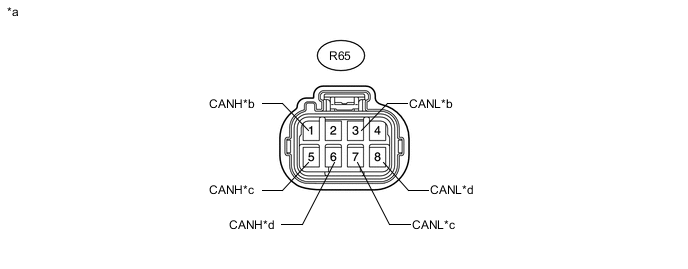
Text in Illustration *a Front view of wire harness connector
(to No. 8 Junction Connector)
*b for Front Multiplex Network Light ECU (Front Controller) *c for No. 9 Junction Connector *d for Front Power Seat Switch RH No. 8 junction Connector Wiring Color Connect to R65-1 (CANH) B Front multiplex network light ECU (front controller) R65-3 (CANL) W R65-5 (CANH) Y No. 9 junction connector R65-7 (CANL) L R65-6 (CANH) R Front power seat switch RH R65-8 (CANL) W -
NO. 9 JUNCTION CONNECTOR
Text in Illustration *a Rear view of wire harness connector
(to No. 9 Junction Connector)
*b for Front Multiplex Network Door ECU RH *c for Rear Multiplex Network Door ECU RH *d for No. 8 Junction Connector *e for No. 10 Junction Connector - - No. 9 Junction Connector Wiring Color Connect to R48-1 (CANH) R Front multiplex network door ECU RH R48-12 (CANL) W R48-2 (CANH) R Rear multiplex network door ECU RH R48-13 (CANL) W R48-3 (CANH) Y No. 8 junction connector R48-14 (CANL) L R48-4 (CANH) B No. 10 junction connector R48-15 (CANL) W -
NO. 10 JUNCTION CONNECTOR
Text in Illustration *a Rear view of wire harness connector
(to No. 10 Junction Connector)
*b for Option Connector (Bus Buffer ECU) (w/ Bus Buffer ECU) *c for Tire Pressure Warning Receiver Assembly (w/ Tire Pressure Warning System) *d for Main Body ECU (Driver Side Junction Block) *e for No. 11 Junction Connector *f for Certification ECU (Smart Key ECU Assembly) *g for Multiplex Tilt and Telescopic ECU *h for No. 1 Meter ECU Sub-assembly *i for Windshield Wiper Switch Assembly *j for Steering Pad Switch Assembly (Steering Pad ECU) *k for Outer Mirror Switch Assembly *l for No. 9 Junction Connector No. 10 Junction Connector Wiring Color Connect to L95-1 (CANH) B Option connector (Bus buffer ECU)*1 L95-12 (CANL) W L95-2 (CANH) B Tire pressure warning receiver assembly*2 L95-13 (CANL) W L95-3 (CANH) B Main body ECU (driver side junction block) L95-14 (CANL) W L95-4 (CANH) B No. 11 junction connector L95-15 (CANL) W L95-5 (CANH) B Certification ECU (smart key ECU assembly) L95-16 (CANL) W L95-6 (CANH) B Multiplex tilt and telescopic ECU L95-17 (CANL) W L95-7 (CANH) B No. 1 meter ECU sub-assembly L95-18 (CANL) W L95-8 (CANH) P Windshield wiper switch assembly L95-19 (CANL) V L95-9 (CANH) R Steering pad switch assembly (steering pad ECU) L95-20 (CANL) W L95-10 (CANH) B Outer mirror switch assembly L95-21 (CANL) W L95-11 (CANH) B No. 9 junction connector L95-22 (CANL) W
-
*1: w/ Bus Buffer ECU
-
*2: w/ Tire Pressure Warning System
-
-
NO. 11 JUNCTION CONNECTOR
Text in Illustration *a Rear view of wire harness connector
(to No. 11 Junction Connector)
*b for Front Power Seat Switch LH *c for No. 12 Junction Connector *d for Rear Multiplex Network Door ECU LH *e for Front Multiplex Network Door ECU LH *f for No. 10 Junction Connector *g for Driving Support ECU Assembly (w/ Pre-crash Safety System) - - No. 11 Junction Connector Wiring Color Connect to S60-1 (CANH) R Front power seat switch LH S60-12 (CANL) W S60-2 (CANH) B No. 12 junction connector S60-13 (CANL) W S60-3 (CANH) R Rear multiplex network door ECU LH S60-14 (CANL) W S60-4 (CANH) R Front multiplex network door ECU LH S60-15 (CANL) W S60-5 (CANH) B No. 10 junction connector S60-16 (CANL) W S60-6 (CANH) B Driving support ECU assembly* S60-17 (CANL) W
-
*: w/ Pre-crash Safety System
-
-
NO. 12 JUNCTION CONNECTOR

Text in Illustration *a Rear view of wire harness connector
(to No. 12 Junction Connector)
*b for Rear Power Seat Switch (w/ Rear Power Seat Control System or Seat Heater System) *c for Power Trunk Lid Control ECU (Luggage Closer Motor Assembly) *d for Luggage Room Junction Block Assembly (Rear Junction Block ECU) *e for No. 11 Junction Connector - - No. 12 Junction Connector Wiring Color Connect to S59-1 (CANH) B Rear power seat switch* S59-12 (CANL) W S59-2 (CANH) B Power trunk lid control ECU (luggage closer motor assembly) S59-13 (CANL) W S59-3 (CANH) B Luggage room junction block assembly (rear junction block ECU) S59-14 (CANL) W S59-4 (CANH) B No. 11 junction connector S59-15 (CANL) W
-
*: w/ Rear Power Seat Control System or Seat Heater System
-
-
NO. 13 JUNCTION CONNECTOR (w/ Pre-crash Safety System)
Text in Illustration *a Rear view of wire harness connector
(to No. 13 Junction Connector)
*b for No. 14 Junction Connector *c for Driver Monitor ECU Assembly (w/ Driver Monitor Camera) *d for Millimeter Wave Radar Sensor Assembly *e for Driving Support ECU Assembly - - No. 13 Junction Connector Wiring Color Connect to L120-1 (CANH) B No. 14 junction connector L120-12 (CANL) W L120-2 (CANH) B Driver monitor ECU assembly* L120-13 (CANL) W L120-3 (CANH) B Millimeter waver radar sensor assembly L120-14 (CANL) W L120-4 (CANH) B Driving support ECU assembly L120-15 (CANL) W
-
*: w/ Driver Monitor Camera
-
-
NO. 14 JUNCTION CONNECTOR (w/ Pre-crash Safety System)
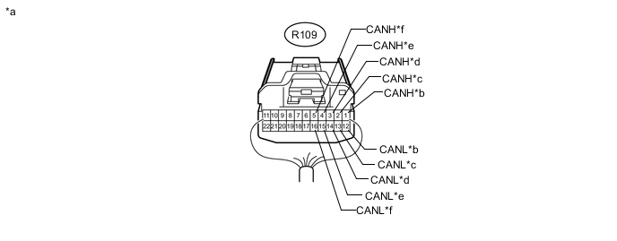
Text in Illustration *a Rear view of wire harness connector
(to No. 14 Junction Connector)
*b for Rear Millimeter Wave Radar Sensor Assembly (w/ Pre-crash Intelligent Headrest) *c for Object Recognition ECU (w/ Driver Monitor Camera) *d for No. 13 Junction Connector *e for No. 1 Night View ECU (w/ Night View System) *f for No. 15 Junction Connector No. 14 Junction Connector Wiring Color Connect to R109-1 (CANH) B Rear millimeter wave radar sensor assembly*1 R109-12 (CANL) W R109-2 (CANH) B Object recognition ECU*2 R109-13 (CANL) W R109-3 (CANH) B No. 13 junction connector R109-14 (CANL) W R109-4 (CANH) B No. 1 night view ECU*3 R109-15 (CANL) W R109-5 (CANH) B No. 15 junction connector R109-16 (CANL) W
-
*1: w/ Pre-crash Intelligent Headrest
-
*2: w/ Driver Monitor Camera
-
*3: w/ Night View System
-
-
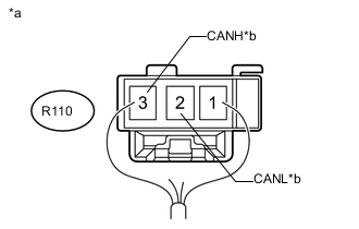
Text in Illustration *a Rear view of wire harness connector
(to No. 15 Junction Connector)
*b for No. 14 Junction Connector NO. 15 JUNCTION CONNECTOR (w/ Pre-crash Safety System)
No. 15 Junction Connector Wiring Color Connect to R110-2 (CANL) W No. 14 junction connector R110-3 (CANH) B -
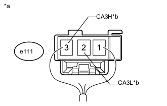
Text in Illustration *a Rear view of wire harness connector
(to No. 16 Junction Connector)
*b for No. 5 Junction Connector NO. 16 JUNCTION CONNECTOR (w/ Pre-crash Intelligent Headrest [except 5- Passenger with Ottoman])
No. 16 Junction Connector Wiring Color Connect to e111-2 (CA3L) G No. 5 junction connector e111-3 (CA3H) R
-
-
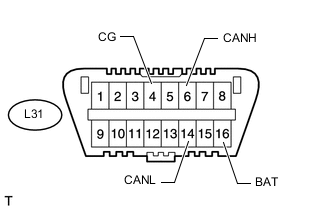
CHECK DLC3
-
Disconnect the cable from the negative (-) auxiliary battery terminal before measuring the resistances of the CAN main wire and CAN branch wire.
CAUTION:
Wait at least 90 seconds after disconnecting the cable from the negative (-) auxiliary battery terminal to disable the SRS system.
Note
-
After turning the power switch off, waiting time may be required before disconnecting the cable from the negative (-) auxiliary battery terminal. Therefore, make sure to read the disconnecting the cable from the negative (-) auxiliary battery terminal notices before proceeding with work Click here.
-
When disconnecting the cable, some systems need to be initialized after the cable is reconnected Click here.
-
-
Measure the resistance according to the value(s) in the table below.
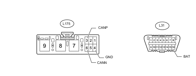
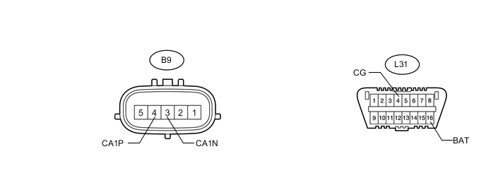
Terminal No. (Symbol) Wiring Color Switch Condition Specified Condition L31-6 (CANH) - L31-14 (CANL) R - G Power switch off 54 to 69 Ω L31-6 (CANH) - L31-4 (CG) R - W-B Power switch off 200 Ω or higher L31-14 (CANL) - L31-4 (CG) G - W-B Power switch off 200 Ω or higher L31-6 (CANH) - L31-16 (BAT) R - B Power switch off 6 kΩ or higher L31-14 (CANL) - L31-16 (BAT) G - B Power switch off 6 kΩ or higher
-
-
CHECK ECM
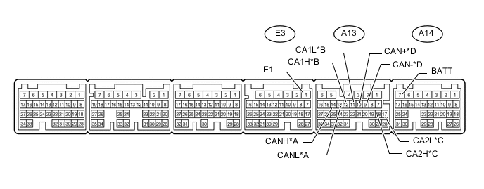
Text in Illustration *A V Bus *B Steering Bus *C Braking and Driving Bus *D HV Engine Bus
-
Disconnect the ECM connectors.
-
Measure the resistance according to the value(s) in the table below.
V Bus Terminal No. (Symbol) Wiring Color Switch Condition Specified Condition A13-14 (CANH) - A13-13 (CANL) B - W Power switch off 108 to 132 Ω A13-14 (CANH) - E3-1 (E1) B - W-B Power switch off 200 Ω or higher A13-13 (CANL) - E3-1 (E1) W - W-B Power switch off 200 Ω or higher A13-14 (CANH) - A14-7 (BATT) B - B Power switch off 6 kΩ or higher A13-13 (CANL) - A14-7 (BATT) W - B Power switch off 6 kΩ or higher Steering Bus Terminal No. (Symbol) Wiring Color Switch Condition Specified Condition A13-12 (CA1H) - A13-11 (CA1L) B - W*1
Y - L*2
Power switch off 108 to 132 Ω A13-12 (CA1H) - E3-1 (E1) B - W-B*1
Y - W-B*2
Power switch off 200 Ω or higher A13-11 (CA1L) - E3-1 (E1) W - W-B*1
L - W-B*2
Power switch off 200 Ω or higher A13-12 (CA1H) - A14-7 (BATT) B - B*1
Y - B*2
Power switch off 6 kΩ or higher A13-11 (CA1L) - A14-7 (BATT) W - B*1
L - B*2
Power switch off 6 kΩ or higher
-
*1: w/ Active Stabilizer Suspension System
-
*2: w/o Active Stabilizer Suspension System
Braking and Driving Bus Terminal No. (Symbol) Wiring Color Switch Condition Specified Condition A13-18 (CA2H) - A13-17 (CA2L) R - G Power switch off 54 to 69 Ω A13-18 (CA2H) - E3-1 (E1) R - W-B Power switch off 200 Ω or higher A13-17 (CA2L) - E3-1 (E1) G - W-B Power switch off 200 Ω or higher A13-18 (CA2H) - A14-7 (BATT) R - B Power switch off 6 kΩ or higher A13-17 (CA2L) - A14-7 (BATT) G - B Power switch off 6 kΩ or higher HV Engine Bus Terminal No. (Symbol) Wiring Color Switch Condition Specified Condition A13-10 (CAN+) - A13-9 (CAN-) B - W Power switch off 108 to 132 Ω A13-10 (CAN+) - E3-1 (E1) B - W-B Power switch off 200 Ω or higher A13-9 (CAN-) - E3-1 (E1) W - W-B Power switch off 200 Ω or higher A13-10 (CAN+) - A14-7 (BATT) B - B Power switch off 6 kΩ or higher A13-9 (CAN-) - A14-7 (BATT) W - B Power switch off 6 kΩ or higher -
-
-
CHECK HYBRID VEHICLE CONTROL ECU
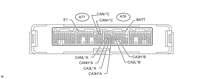
Text in Illustration *A V Bus *B Braking and Driving Bus *C HV Engine Bus - -
-
Disconnect the hybrid vehicle control ECU connectors.
-
Measure the resistance according to the value(s) in the table below.
V Bus Terminal No. (Symbol) Wiring Color Switch Condition Specified Condition A76-15 (CANH) - A76-16 (CANL) Y - L Power switch off 108 to 132 Ω A76-15 (CANH) - A77-7 (E1) Y - W-B Power switch off 200 Ω or higher A76-16 (CANL) - A77-7 (E1) L - W-B Power switch off 200 Ω or higher A76-15 (CANH) - A76-1 (BATT) Y - B-W Power switch off 6 kΩ or higher A76-16 (CANL) - A76-1 (BATT) L - B-W Power switch off 6 kΩ or higher A77-13 (CA3H) - A77-14 (CA3L) B - W Power switch off 108 to 132 Ω A77-13 (CA3H) - A77-7 (E1) B - W-B Power switch off 200 Ω or higher A77-14 (CA3L) - A77-7 (E1) W - W-B Power switch off 200 Ω or higher A77-13 (CA3H) - A76-1 (BATT) B - B-W Power switch off 6 kΩ or higher A77-14 (CA3L) - A76-1 (BATT) W - B-W Power switch off 6 kΩ or higher Braking and Driving Bus Terminal No. (Symbol) Wiring Color Switch Condition Specified Condition A76-11 (CA2H) - A76-12 (CA2L) B - W Power switch off 54 to 69 Ω A76-11 (CA2H) - A77-7 (E1) B - W-B Power switch off 200 Ω or higher A76-12 (CA2L) - A77-7 (E1) W - W-B Power switch off 200 Ω or higher A76-11 (CA2H) - A76-1 (BATT) B - B-W Power switch off 6 kΩ or higher A76-12 (CA2L) - A76-1 (BATT) W - B-W Power switch off 6 kΩ or higher HV Engine Bus Terminal No. (Symbol) Wiring Color Switch Condition Specified Condition A77-8 (CAN+) - A77-9 (CAN-) B - W Power switch off 108 to 132 Ω A77-8 (CAN+) - A77-7 (E1) B - W-B Power switch off 200 Ω or higher A77-9 (CAN-) - A77-7 (E1) W - W-B Power switch off 200 Ω or higher A77-8 (CAN+) - A76-1 (BATT) B - B-W Power switch off 6 kΩ or higher A77-9 (CAN-) - A76-1 (BATT) W - B-W Power switch off 6 kΩ or higher
-
-
CHECK SKID CONTROL ECU ASSEMBLY
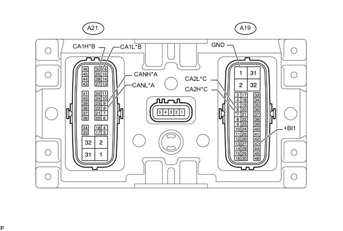
Text in Illustration *A V Bus *B Steering Bus *C Braking and Driving Bus - -
-
Disconnect the skid control ECU assembly connectors.
-
Measure the resistance according to the value(s) in the table below.
V Bus Terminal No. (Symbol) Wiring Color Switch Condition Specified Condition A21-9 (CANH) - A21-8 (CANL) B - W Power switch off 54 to 69 Ω A21-9 (CANH) - A19-1 (GND) B - W-B Power switch off 200 Ω or higher A21-8 (CANL) - A19-1 (GND) W - W-B Power switch off 200 Ω or higher A21-9 (CANH) - A19-43 (+BI1) B - B Power switch off 6 kΩ or higher A21-8 (CANL) - A19-43 (+BI1) W - B Power switch off 6 kΩ or higher Steering Bus Terminal No. (Symbol) Wiring Color Switch Condition Specified Condition A21-30 (CA1H) - A21-29 (CA1L) R - G Power switch off 54 to 69 Ω A21-30 (CA1H) - A19-1 (GND) R - W-B Power switch off 200 Ω or higher A21-29 (CA1L) - A19-1 (GND) G - W-B Power switch off 200 Ω or higher A21-30 (CA1H) - A19-43 (+BI1) R - B Power switch off 6 kΩ or higher A21-29 (CA1L) - A19-43 (+BI1) G - B Power switch off 6 kΩ or higher Braking and Driving Bus Terminal No. (Symbol) Wiring Color Switch Condition Specified Condition A19-7 (CA2H) - A19-6 (CA2L) Y - L Power switch off 54 to 69 Ω A19-7 (CA2H) - A19-1 (GND) Y - W-B Power switch off 200 Ω or higher A19-6 (CA2L) - A19-1 (GND) L - W-B Power switch off 200 Ω or higher A19-7 (CA2H) - A19-43 (+BI1) Y - B Power switch off 6 kΩ or higher A19-6 (CA2L) - A19-43 (+BI1) L - B Power switch off 6 kΩ or higher
-
-
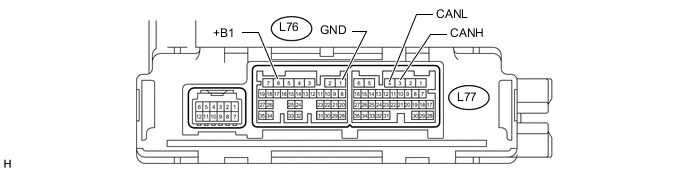
CHECK AIR CONDITIONING AMPLIFIER ASSEMBLY
-
Disconnect the air conditioning amplifier assembly connectors.
-
Measure the resistance according to the value(s) in the table below.
Terminal No. (Symbol) Wiring Color Switch Condition Specified Condition L77-3 (CANH) - L77-4 (CANL) R - G Power switch off 54 to 69 Ω L77-3 (CANH) - L76-1 (GND) R - W-B Power switch off 200 Ω or higher L77-4 (CANL) - L76-1 (GND) G - W-B Power switch off 200 Ω or higher L77-3 (CANH) - L76-6 (+B1) R - L Power switch off 6 kΩ or higher L77-4 (CANL) - L76-6 (+B1) G - L Power switch off 6 kΩ or higher
-
-
CHECK MAIN BODY ECU (DRIVER SIDE JUNCTION BLOCK)
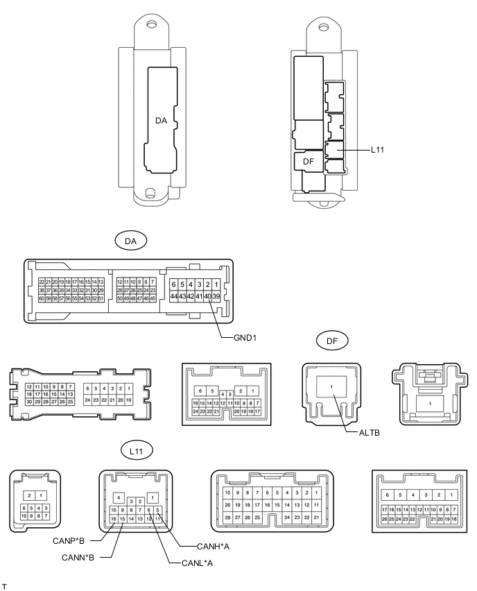
Text in Illustration *A V Bus *B MS Bus
-
Disconnect the main body ECU (driver side junction block) connectors.
-
Measure the resistance according to the value(s) in the table below.
V Bus Terminal No. (Symbol) Wiring Color Switch Condition Specified Condition L11-5 (CANH) - L11-6 (CANL) R - G Power switch off 54 to 69 Ω L11-5 (CANH) - DA-40 (GND1) R - W-B Power switch off 200 Ω or higher L11-6 (CANL) - DA-40 (GND1) G - W-B Power switch off 200 Ω or higher L11-5 (CANH) - DF-1 (ALTB) R - B Power switch off 6 kΩ or higher L11-6 (CANL) - DF-1 (ALTB) G - B Power switch off 6 kΩ or higher MS Bus Terminal No. (Symbol) Wiring Color Switch Condition Specified Condition L11-16 (CANP) - L11-15 (CANN) B - W Power switch off 54 to 69 Ω L11-16 (CANP) - DA-40 (GND1) B - W-B Power switch off 200 Ω or higher L11-15 (CANN) - DA-40 (GND1) W - W-B Power switch off 200 Ω or higher L11-16 (CANP) - DF-1 (ALTB) B - B Power switch off 6 kΩ or higher L11-15 (CANN) - DF-1 (ALTB) W - B Power switch off 6 kΩ or higher
-
-
CHECK NO. 1 METER ECU SUB-ASSEMBLY

Text in Illustration *A V Bus *B MS Bus
-
Disconnect the No. 1 meter ECU sub-assembly connector.
-
Measure the resistance according to the value(s) in the table below.
V Bus Terminal No. (Symbol) Wiring Color Switch Condition Specified Condition L124-20 (CANH) - L124-21 (CANL) R - G Power switch off 54 to 69 Ω L124-20 (CANH) - L124-18 (ES) R - BR Power switch off 200 Ω or higher L124-21 (CANL) - L124-18 (ES) G - BR Power switch off 200 Ω or higher L124-20 (CANH) - L124-13 (B) R - P Power switch off 6 kΩ or higher L124-21 (CANL) - L124-13 (B) G - P Power switch off 6 kΩ or higher MS Bus Terminal No. (Symbol) Wiring Color Switch Condition Specified Condition L124-22 (CANP) - L124-23 (CANN) B - W Power switch off 54 to 69 Ω L124-22 (CANP) - L124-18 (ES) B - BR Power switch off 200 Ω or higher L124-23 (CANN) - L124-18 (ES) W - BR Power switch off 200 Ω or higher L124-22 (CANP) - L124-13 (B) B - P Power switch off 6 kΩ or higher L124-23 (CANN) - L124-13 (B) W - P Power switch off 6 kΩ or higher
-
-
CHECK CENTER AIRBAG SENSOR ASSEMBLY
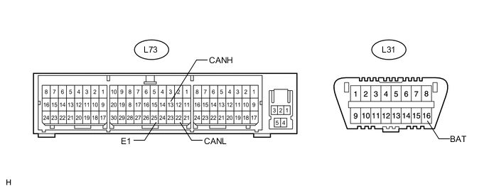
-
Disconnect the center airbag sensor assembly connector Click here.
-
Measure the resistance according to the value(s) in the table below.
Terminal No. (Symbol) Wiring Color Switch Condition Specified Condition L73-13 (CANH) - L73-22 (CANL) R - G Power switch off 108 to 132 Ω L73-13 (CANH) - L73-25 (E1) R - W-B Power switch off 200 Ω or higher L73-22 (CANL) - L73-25 (E1) G - W-B Power switch off 200 Ω or higher L73-13 (CANH) - L31-16 (BAT) R - B Power switch off 6 kΩ or higher L73-22 (CANL) - L31-16 (BAT) G - B Power switch off 6 kΩ or higher
-
-
CHECK HEADLIGHT SWIVEL ECU ASSEMBLY
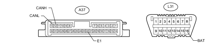
-
Disconnect the headlight swivel ECU assembly connector.
-
Measure the resistance according to the value(s) in the table below.
Terminal No. (Symbol) Wiring Color Switch Condition Specified Condition A37-12 (CANH) - A37-13 (CANL) B - W Power switch off 54 to 69 Ω A37-12 (CANH) - A37-22 (E1) B - W-B Power switch off 200 Ω or higher A37-13 (CANL) - A37-22 (E1) W - W-B Power switch off 200 Ω or higher A37-12 (CANH) - L31-16 (BAT) B - B Power switch off 6 kΩ or higher A37-13 (CANL) - L31-16 (BAT) W - B Power switch off 6 kΩ or higher
-
-
CHECK MULTI-MEDIA MODULE RECEIVER ASSEMBLY
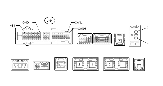
-
Disconnect the multi-media module receiver assembly connector.
-
Measure the resistance according to the value(s) in the table below.
Terminal No. (Symbol) Wiring Color Switch Condition Specified Condition L164-1 (CANH) - L164-2 (CANL) R - G Power switch off 54 to 69 Ω L164-1 (CANH) - L164-12 (GND1) R - W-B Power switch off 200 Ω or higher L164-2 (CANL) - L164-12 (GND1) G - W-B Power switch off 200 Ω or higher L164-1 (CANH) - L164-17 (+B1) R - R Power switch off 6 kΩ or higher L164-2 (CANL) - L164-17 (+B1) G - R Power switch off 6 kΩ or higher
-
-
CHECK STEERING ANGLE SENSOR
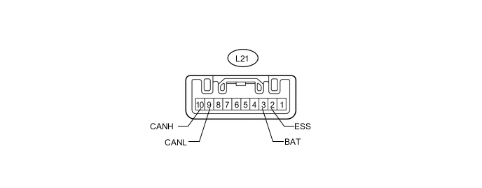
-
Disconnect the steering angle sensor connector.
-
Measure the resistance according to the value(s) in the table below.
Terminal No. (Symbol) Wiring Color Switch Condition Specified Condition L21-10 (CANH) - L21-9 (CANL) R - W Power switch off 54 to 69 Ω L21-10 (CANH) - L21-2 (ESS) R - W-B Power switch off 200 Ω or higher L21-9 (CANL) - L21-2 (ESS) W - W-B Power switch off 200 Ω or higher L21-10 (CANH) - L21-3 (BAT) R - R Power switch off 6 kΩ or higher L21-9 (CANL) - L21-3 (BAT) W - R Power switch off 6 kΩ or higher
-
-
CHECK YAW RATE SENSOR
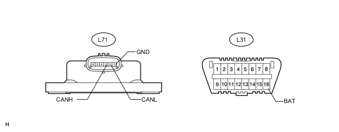
-
Disconnect the yaw rate sensor connector.
-
Measure the resistance according to the value(s) in the table below.
Terminal No. (Symbol) Wiring Color Switch Condition Specified Condition L71-3 (CANH) - L71-2 (CANL) B - W Power switch off 54 to 69 Ω L71-3 (CANH) - L71-1 (GND) B - W-B Power switch off 200 Ω or higher L71-2 (CANL) - L71-1 (GND) W - W-B Power switch off 200 Ω or higher L71-3 (CANH) - L31-16 (BAT) B - B Power switch off 6 kΩ or higher L71-2 (CANL) - L31-16 (BAT) W - B Power switch off 6 kΩ or higher
-
-
CHECK POWER STEERING ECU ASSEMBLY
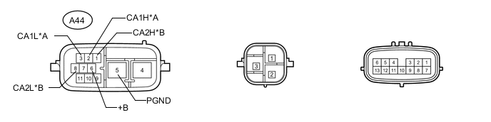
Text in Illustration *A Steering Bus *B Braking and Driving Bus
-
Disconnect the power steering ECU assembly connector.
-
Measure the resistance according to the value(s) in the table below.
Steering Bus Terminal No. (Symbol) Wiring Color Switch Condition Specified Condition A44-2 (CA1H) - A44-3 (CA1L) B - W Power switch off 108 to 132 Ω A44-2 (CA1H) - A44-5 (PGND) B - W-B Power switch off 200 Ω or higher A44-3 (CA1L) - A44-5 (PGND) W - W-B Power switch off 200 Ω or higher A44-2 (CA1H) - A44-6 (+B) B - R Power switch off 6 kΩ or higher A44-3 (CA1L) - A44-6 (+B) W - R Power switch off 6 kΩ or higher Braking and Driving Bus Terminal No. (Symbol) Wiring Color Switch Condition Specified Condition A44-1 (CA2H) - A44-8 (CA2L) R - G Power switch off 108 to 132 Ω A44-1 (CA2H) - A44-5 (PGND) R - W-B Power switch off 200 Ω or higher A44-8 (CA2L) - A44-5 (PGND) G - W-B Power switch off 200 Ω or higher A44-1 (CA2H) - A44-6 (+B) R - R Power switch off 6 kΩ or higher A44-8 (CA2L) - A44-6 (+B) G - R Power switch off 6 kΩ or higher
-
-
CHECK STEERING CONTROL ECU
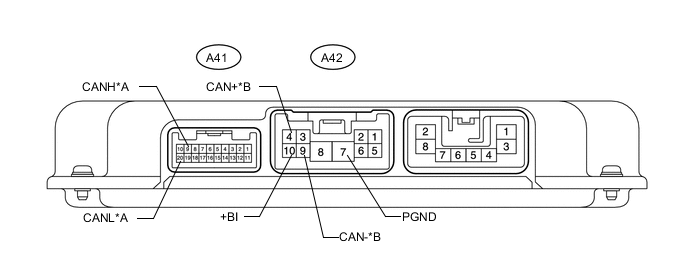
Text in Illustration *A Steering Bus *B Braking and Driving Bus
-
Disconnect the steering control ECU connectors.
-
Measure the resistance according to the value(s) in the table below.
Steering Bus Terminal No. (Symbol) Wiring Color Switch Condition Specified Condition A41-9 (CANH) - A41-20 (CANL) B - W Power switch off 54 to 69 Ω A41-9 (CANH) - A42-7 (PGND) B - W-B Power switch off 200 Ω or higher A41-20 (CANL) - A42-7 (PGND) W - W-B Power switch off 200 Ω or higher A41-9 (CANH) - A42-10 (+BI) B - R Power switch off 6 kΩ or higher A41-20 (CANL) - A42-10 (+BI) W - R Power switch off 6 kΩ or higher Braking and Driving Bus Terminal No. (Symbol) Wiring Color Switch Condition Specified Condition A42-4 (CAN+) - A42-9 (CAN-) Y - L Power switch off 54 to 69 Ω A42-4 (CAN+) - A42-7 (PGND) Y - W-B Power switch off 200 Ω or higher A42-9 (CAN-) - A42-7 (PGND) L - W-B Power switch off 200 Ω or higher A42-4 (CAN+) - A42-10 (+BI) Y - R Power switch off 6 kΩ or higher A42-9 (CAN-) - A42-10 (+BI) L - R Power switch off 6 kΩ or higher
-
-
CHECK SUSPENSION CONTROL ECU
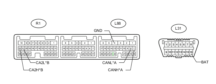
Text in Illustration *A Steering Bus *B Braking and Driving Bus
-
Disconnect the suspension control ECU connectors.
-
Measure the resistance according to the value(s) in the table below.
Steering Bus Terminal No. (Symbol) Wiring Color Switch Condition Specified Condition L88-7 (CANH) - L88-8 (CANL) B - W Power switch off 54 to 69 Ω L88-7 (CANH) - L88-4 (GND) B - W-B Power switch off 200 Ω or higher L88-8 (CANL) - L88-4 (GND) W - W-B Power switch off 200 Ω or higher L88-7 (CANH) - L31-16 (BAT) B - B Power switch off 6 kΩ or higher L88-8 (CANL) - L31-16 (BAT) W - B Power switch off 6 kΩ or higher Braking and Driving Bus Terminal No. (Symbol) Wiring Color Switch Condition Specified Condition R1-22 (CA2H) - R1-21 (CA2L) B - W Power switch off 54 to 69 Ω R1-22 (CA2H) - L88-4 (GND) B - W-B Power switch off 200 Ω or higher R1-21 (CA2L) - L88-4 (GND) W - W-B Power switch off 200 Ω or higher R1-22 (CA2H) - L31-16 (BAT) B - B Power switch off 6 kΩ or higher R1-21 (CA2L) - L31-16 (BAT) W - B Power switch off 6 kΩ or higher
-
-
CHECK NETWORK GATEWAY ECU (w/ Pre-crash Intelligent Headrest)
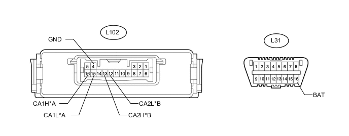
Text in Illustration *A Steering Bus *B WIL Bus
-
Disconnect the network gateway ECU connector.
-
Measure the resistance according to the value(s) in the table below.
Steering Bus Terminal No. (Symbol) Wiring Color Switch Condition Specified Condition L102-16 (CA1H) - L102-15 (CA1L) B - W Power switch off 54 to 69 Ω L102-16 (CA1H) - L102-4 (GND) B - W-B Power switch off 200 Ω or higher L102-15 (CA1L) - L102-4 (GND) W - W-B Power switch off 200 Ω or higher L102-16 (CA1H) - L31-16 (BAT) B - B Power switch off 6 kΩ or higher L102-15 (CA1L) - L31-16 (BAT) W - B Power switch off 6 kΩ or higher WIL Bus Terminal No. (Symbol) Wiring Color Switch Condition Specified Condition L102-13 (CA2H) - L102-12 (CA2L) B - W Power switch off 54 to 69 Ω L102-13 (CA2H) - L102-4 (GND) B - W-B Power switch off 200 Ω or higher L102-12 (CA2L) - L102-4 (GND) W - W-B Power switch off 200 Ω or higher L102-13 (CA2H) - L31-16 (BAT) B - B Power switch off 6 kΩ or higher L102-12 (CA2L) - L31-16 (BAT) W - B Power switch off 6 kΩ or higher
-
-
CHECK FRONT ACTIVE STABILIZER CONTROL ECU ASSEMBLY (w/ Active Stabilizer Suspension System)
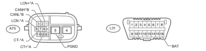
Text in Illustration *A Steering Bus *B Braking and Driving Bus
-
Disconnect the front active stabilizer control ECU assembly connector.
-
Measure the resistance according to the value(s) in the table below.
Steering Bus Terminal No. (Symbol) Wiring Color Switch Condition Specified Condition A75-10 (CT+) - A75-7 (CT-) B - W Power switch off 108 to 132 Ω A75-10 (CT+) - A75-5 (PGND) B - W-B Power switch off 200 Ω or higher A75-7 (CT-) - A75-5 (PGND) W - W-B Power switch off 200 Ω or higher A75-10 (CT+) - L31-16 (BAT) B - B Power switch off 6 kΩ or higher A75-7 (CT-) - L31-16 (BAT) W - B Power switch off 6 kΩ or higher A75-1 (LCN+) - A75-8 (LCN-) R - G Power switch off 108 to 132 Ω A75-1 (LCN+) - A75-5 (PGND) R - W-B Power switch off 200 Ω or higher A75-8 (LCN-) - A75-5 (PGND) G - W-B Power switch off 200 Ω or higher A75-1 (LCN+) - L31-16 (BAT) R - B Power switch off 6 kΩ or higher A75-8 (LCN-) - L31-16 (BAT) G - B Power switch off 6 kΩ or higher Braking and Driving Bus Terminal No. (Symbol) Wiring Color Switch Condition Specified Condition A75-2 (CANH) - A75-3 (CANL) Y - L Power switch off 54 to 69 Ω A75-2 (CANH) - A75-5 (PGND) Y - W-B Power switch off 200 Ω or higher A75-3 (CANL) - A75-5 (PGND) L - W-B Power switch off 200 Ω or higher A75-2 (CANH) - L31-16 (BAT) Y - B Power switch off 6 kΩ or higher A75-3 (CANL) - L31-16 (BAT) L - B Power switch off 6 kΩ or higher
-
-
CHECK REAR ACTIVE STABILIZER CONTROL ECU ASSEMBLY (w/ Active Stabilizer Suspension System)
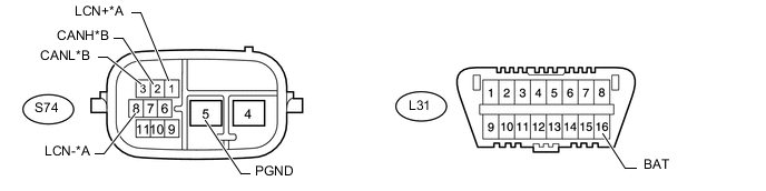
Text in Illustration *A Steering Bus *B Braking and Driving Bus
-
Disconnect the rear active stabilizer control ECU assembly connector.
-
Measure the resistance according to the value(s) in the table below.
Steering Bus Terminal No. (Symbol) Wiring Color Switch Condition Specified Condition S74-1 (LCN+) - S74-8 (LCN-) B - W Power switch off 54 to 69 Ω S74-1 (LCN+) - S74-5 (PGND) B - W-B Power switch off 200 Ω or higher S74-8 (LCN-) - S74-5 (PGND) W - W-B Power switch off 200 Ω or higher S74-1 (LCN+) - L31-16 (BAT) B - B Power switch off 6 kΩ or higher S74-8 (LCN-) - L31-16 (BAT) W - B Power switch off 6 kΩ or higher Braking and Driving Bus Terminal No. (Symbol) Wiring Color Switch Condition Specified Condition S74-2 (CANH) - S74-3 (CANL) Y - L Power switch off 54 to 69 Ω S74-2 (CANH) - S74-5 (PGND) Y - W-B Power switch off 200 Ω or higher S74-3 (CANL) - S74-5 (PGND) L - W-B Power switch off 200 Ω or higher S74-2 (CANH) - L31-16 (BAT) Y - B Power switch off 6 kΩ or higher S74-3 (CANL) - L31-16 (BAT) L - B Power switch off 6 kΩ or higher
-
-
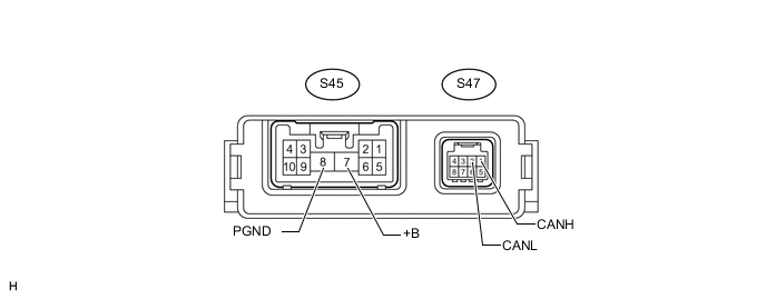
CHECK SEAT BELT CONTROL ECU (w/ Pre-crash Safety System)
-
Disconnect the seat belt control ECU connectors.
-
Measure the resistance according to the value(s) in the table below.
Terminal No. (Symbol) Wiring Color Switch Condition Specified Condition S47-1 (CANH) - S47-2 (CANL) B - W Power switch off 54 to 69 Ω S47-1 (CANH) - S45-8 (PGND) B - W-B Power switch off 200 Ω or higher S47-2 (CANL) - S45-8 (PGND) W - W-B Power switch off 200 Ω or higher S47-1 (CANH) - S45-7 (+B) B - B Power switch off 6 kΩ or higher S47-2 (CANL) - S45-7 (+B) W - B Power switch off 6 kΩ or higher
-
-
CHECK DRIVING SUPPORT ECU ASSEMBLY (w/ Pre-crash Safety System)
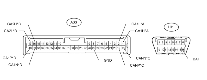
Text in Illustration *A Steering Bus *B Braking and Driving Bus *C MS Bus *D Parking Assist Bus
-
Disconnect the driving support ECU assembly connector.
-
Measure the resistance according to the value(s) in the table below.
Steering Bus Terminal No. (Symbol) Wiring Color Switch Condition Specified Condition A33-1 (CA1H) - A33-2 (CA1L) B - W Power switch off 54 to 69 Ω A33-1 (CA1H) - A33-25 (GND) B - W-B Power switch off 200 Ω or higher A33-2 (CA1L) - A33-25 (GND) W - W-B Power switch off 200 Ω or higher A33-1 (CA1H) - L31-16 (BAT) B - B Power switch off 6 kΩ or higher A33-2 (CA1L) - L31-16 (BAT) W - B Power switch off 6 kΩ or higher Braking and Driving Bus Terminal No. (Symbol) Wiring Color Switch Condition Specified Condition A33-16 (CA2H) - A33-17 (CA2L) B - W Power switch off 54 to 69 Ω A33-16 (CA2H) - A33-25 (GND) B - W-B Power switch off 200 Ω or higher A33-17 (CA2L) - A33-25 (GND) W - W-B Power switch off 200 Ω or higher A33-16 (CA2H) - L31-16 (BAT) B - B Power switch off 6 kΩ or higher A33-17 (CA2L) - L31-16 (BAT) W - B Power switch off 6 kΩ or higher MS Bus Terminal No. (Symbol) Wiring Color Switch Condition Specified Condition A33-19 (CANP) - A33-18 (CANN) B - W Power switch off 54 to 69 Ω A33-19 (CANP) - A33-25 (GND) B - W-B Power switch off 200 Ω or higher A33-18 (CANN) - A33-25 (GND) W - W-B Power switch off 200 Ω or higher A33-19 (CANP) - L31-16 (BAT) B - B Power switch off 6 kΩ or higher A33-18 (CANN) - L31-16 (BAT) W - B Power switch off 6 kΩ or higher Parking Assist Bus Terminal No. (Symbol) Wiring Color Switch Condition Specified Condition A33-40 (CA1P) - A33-39 (CA1N) B - W Power switch off 54 to 69 Ω A33-40 (CA1P) - A33-25 (GND) B - W-B Power switch off 200 Ω or higher A33-39 (CA1N) - A33-25 (GND) W - W-B Power switch off 200 Ω or higher A33-40 (CA1P) - L31-16 (BAT) B - B Power switch off 6 kΩ or higher A33-39 (CA1N) - L31-16 (BAT) W - B Power switch off 6 kΩ or higher
-
-
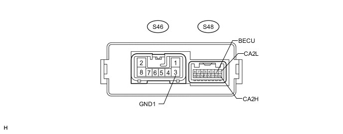
CHECK PARKING BRAKE ECU ASSEMBLY
-
Disconnect the parking brake ECU assembly connectors.
-
Measure the resistance according to the value(s) in the table below.
Terminal No. (Symbol) Wiring Color Switch Condition Specified Condition S48-9 (CA2H) - S48-1 (CA2L) B - W Power switch off 108 to 132 Ω S48-9 (CA2H) - S46-3 (GND1) B - W-B Power switch off 200 Ω or higher S48-1 (CA2L) - S46-3 (GND1) W - W-B Power switch off 200 Ω or higher S48-9 (CA2H) - S48-2 (BECU) B - BE Power switch off 6 kΩ or higher S48-1 (CA2L) - S48-2 (BECU) W - BE Power switch off 6 kΩ or higher
-
-
CHECK BLIND SPOT MONITOR SENSOR LH (w/ Blind Spot Monitor System)
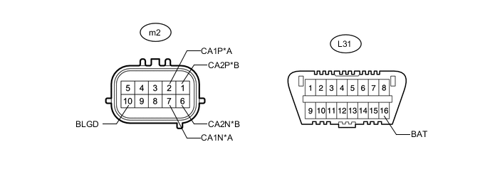
Text in Illustration *A Braking and Driving Bus *B Sensor Bus
-
Disconnect the blind spot monitor sensor LH connector.
-
Measure the resistance according to the value(s) in the table below.
Braking and Driving Bus Terminal No. (Symbol) Wiring Color Switch Condition Specified Condition m2-2 (CA1P) - m2-7 (CA1N) Y - B Power switch off 54 to 69 Ω m2-2 (CA1P) - m2-10 (BLGD) Y - W-B Power switch off 200 Ω or higher m2-7 (CA1N) - m2-10 (BLGD) B - W-B Power switch off 200 Ω or higher m2-2 (CA1P) - L31-16 (BAT) Y - B Power switch off 6 kΩ or higher m2-7 (CA1N) - L31-16 (BAT) B - B Power switch off 6 kΩ or higher Sensor Bus Terminal No. (Symbol) Wiring Color Switch Condition Specified Condition m2-1 (CA2P) - m2-6 (CA2N) B - Y Power switch off 108 to 132 Ω m2-1 (CA2P) - m2-10 (BLGD) B - W-B Power switch off 200 Ω or higher m2-6 (CA2N) - m2-10 (BLGD) Y - W-B Power switch off 200 Ω or higher m2-1 (CA2P) - L31-16 (BAT) B - B Power switch off 6 kΩ or higher m2-6 (CA2N) - L31-16 (BAT) Y - B Power switch off 6 kΩ or higher
-
-
CHECK BLIND SPOT MONITOR SENSOR RH (w/ Blind Spot Monitor System)
*1 BRGD
-
Disconnect the blind spot monitor sensor RH connector.
-
Measure the resistance according to the value(s) in the table below.
Terminal No. (Symbol) Wiring Color Switch Condition Specified Condition m1-1 (CA2P) - m1-6 (CA2N) B - Y Power switch off 108 to 132 Ω m1-1 (CA2P) - m1-10 (BRGD) B - W-B Power switch off 200 Ω or higher m1-6 (CA2N) - m1-10 (BRGD) Y - W-B Power switch off 200 Ω or higher m1-1 (CA2P) - L31-16 (BAT) B - B Power switch off 6 kΩ or higher m1-6 (CA2N) - L31-16 (BAT) Y - B Power switch off 6 kΩ or higher
-
-
CHECK CLEARANCE WARNING ECU ASSEMBLY
-
Disconnect the clearance warning ECU assembly connector.
-
Measure the resistance according to the value(s) in the table below.
Terminal No. (Symbol) Wiring Color Switch Condition Specified Condition L159-3 (CA2H) - L159-5 (CA2L) B - W Power switch off 54 to 69 Ω L159-3 (CA2H) - L159-17 (E) B - W-B Power switch off 200 Ω or higher L159-5 (CA2L) - L159-17 (E) W - W-B Power switch off 200 Ω or higher L159-3 (CA2H) - L31-16 (BAT) B - B Power switch off 6 kΩ or higher L159-5 (CA2L) - L31-16 (BAT) W - B Power switch off 6 kΩ or higher
-
-
CHECK FRONT MULTIPLEX NETWORK LIGHT ECU (FRONT CONTROLLER)
-
Disconnect the front multiplex network light ECU (front controller) connector.
-
Measure the resistance according to the value(s) in the table below.
Terminal No. (Symbol) Wiring Color Switch Condition Specified Condition A50-3 (CANP) - A50-4 (CANN) B - W Power switch off 108 to 132 Ω A50-3 (CANP) - A50-2 (E) B - W-B Power switch off 200 Ω or higher A50-4 (CANN) - A50-2 (E) W - W-B Power switch off 200 Ω or higher A50-3 (CANP) - A50-1 (FMB3) B - LG Power switch off 6 kΩ or higher A50-4 (CANN) - A50-1 (FMB3) W - LG Power switch off 6 kΩ or higher
-
-
CHECK OUTER MIRROR SWITCH ASSEMBLY

-
Disconnect the outer mirror switch assembly connector.
-
Measure the resistance according to the value(s) in the table below.
Terminal No. (Symbol) Wiring Color Switch Condition Specified Condition L6-2 (CANP) - L6-3 (CANN) B - W Power switch off 54 to 69 Ω L6-2 (CANP) - L6-1 (E) B - W-B Power switch off 200 Ω or higher L6-3 (CANN) - L6-1 (E) W - W-B Power switch off 200 Ω or higher L6-2 (CANP) - L6-12 (B) B - B Power switch off 6 kΩ or higher L6-3 (CANN) - L6-12 (B) W - B Power switch off 6 kΩ or higher
-
-
CHECK STEERING PAD SWITCH WITH MODULATOR ASSEMBLY (STEERING PAD ECU)
Tech Tips
As there is a spiral cable sub-assembly between the steering pad ECU and the vehicle harness connector, a direct inspection of the steering pad ECU side of the vehicle harness connector cannot be performed.
*1 NOSB
-
Disconnect the spiral cable sub-assembly connector.
-
Measure the resistance according to the value(s) in the table below.
Terminal No. (Symbol) Wiring Color Switch Condition Specified Condition L126-10 (CANP) - L126-9 (CANN) R - W Power switch off 54 to 69 Ω L126-10 (CANP) - L126-3 (NOSB) R - W-B Power switch off 200 Ω or higher L126-9 (CANN) - L126-3 (NOSB) W - W-B Power switch off 200 Ω or higher L126-10 (CANP) - L126-7 (+B) R - B Power switch off 6 kΩ or higher L126-9 (CANN) - L126-7 (+B) W - B Power switch off 6 kΩ or higher
-
-
CHECK MULTIPLEX TILT AND TELESCOPIC ECU
-
Disconnect the multiplex tilt and telescopic ECU connector.
-
Measure the resistance according to the value(s) in the table below.
Terminal No. (Symbol) Wiring Color Switch Condition Specified Condition L34-5 (CANP) - L34-14 (CANN) B - W Power switch off 54 to 69 Ω L34-5 (CANP) - L34-11 (GND) B - W-B Power switch off 200 Ω or higher L34-14 (CANN) - L34-11 (GND) W - W-B Power switch off 200 Ω or higher L34-5 (CANP) - L34-2 (+B) B - B Power switch off 6 kΩ or higher L34-14 (CANN) - L34-2 (+B) W - B Power switch off 6 kΩ or higher
-
-
CHECK CERTIFICATION ECU (SMART KEY ECU ASSEMBLY)
-
Disconnect the certification ECU (smart key ECU assembly) connector.
-
Measure the resistance according to the value(s) in the table below.
Terminal No. (Symbol) Wiring Color Switch Condition Specified Condition L15-27 (CANH) - L15-28 (CANL) B - W Power switch off 54 to 69 Ω L15-27 (CANH) - L15-17 (E) B - W-B Power switch off 200 Ω or higher L15-28 (CANL) - L15-17 (E) W - W-B Power switch off 200 Ω or higher L15-27 (CANH) - L15-1 (+B1) B - L Power switch off 6 kΩ or higher L15-28 (CANL) - L15-1 (+B1) W - L Power switch off 6 kΩ or higher
-
-
CHECK FRONT MULTIPLEX NETWORK DOOR ECU LH
-
Disconnect the front multiplex network door ECU LH connector.
-
Measure the resistance according to the value(s) in the table below.
Terminal No. (Symbol) Wiring Color Switch Condition Specified Condition N10-9 (CANP) - N10-10 (CANN) R - W Power switch off 54 to 69 Ω N10-9 (CANP) - N10-1 (GND) R - W-B Power switch off 200 Ω or higher N10-10 (CANN) - N10-1 (GND) W - W-B Power switch off 200 Ω or higher N10-9 (CANP) - N10-11 (CPUB) R - B Power switch off 6 kΩ or higher N10-10 (CANN) - N10-11 (CPUB) W - B Power switch off 6 kΩ or higher
-
-
CHECK FRONT MULTIPLEX NETWORK DOOR ECU RH
-
Disconnect the front multiplex network door ECU RH connector.
-
Measure the resistance according to the value(s) in the table below.
Terminal No. (Symbol) Wiring Color Switch Condition Specified Condition N1-9 (CANP) - N1-10 (CANN) R - W Power switch off 54 to 69 Ω N1-9 (CANP) - N1-1 (GND) R - W-B Power switch off 200 Ω or higher N1-10 (CANN) - N1-1 (GND) W - W-B Power switch off 200 Ω or higher N1-9 (CANP) - N1-11 (CPUB) R - R Power switch off 6 kΩ or higher N1-10 (CANN) - N1-11 (CPUB) W - R Power switch off 6 kΩ or higher
-
-
CHECK REAR MULTIPLEX NETWORK DOOR ECU LH

-
Disconnect the rear multiplex network door ECU LH connector.
-
Measure the resistance according to the value(s) in the table below.
Terminal No. (Symbol) Wiring Color Switch Condition Specified Condition O14-9 (CANP) - O14-10 (CANN) R - W Power switch off 54 to 69 Ω O14-9 (CANP) - O14-1 (GND) R - W-B Power switch off 200 Ω or higher O14-10 (CANN) - O14-1 (GND) W - W-B Power switch off 200 Ω or higher O14-9 (CANP) - O14-11 (CPUB) R - R Power switch off 6 kΩ or higher O14-10 (CANN) - O14-11 (CPUB) W - R Power switch off 6 kΩ or higher
-
-
CHECK REAR MULTIPLEX NETWORK DOOR ECU RH
-
Disconnect the rear multiplex network door ECU RH connector.
-
Measure the resistance according to the value(s) in the table below.
Terminal No. (Symbol) Wiring Color Switch Condition Specified Condition O3-9 (CANP) - O3-10 (CANN) R - W Power switch off 54 to 69 Ω O3-9 (CANP) - O3-1 (GND) R - W-B Power switch off 200 Ω or higher O3-10 (CANN) - O3-1 (GND) W - W-B Power switch off 200 Ω or higher O3-9 (CANP) - O3-11 (CPUB) R - R Power switch off 6 kΩ or higher O3-10 (CANN) - O3-11 (CPUB) W - R Power switch off 6 kΩ or higher
-
-
CHECK FRONT POWER SEAT SWITCH LH

-
Disconnect the front power swat switch LH connectors.
-
Measure the resistance according to the value(s) in the table below.
Terminal No. (Symbol) Wiring Color Switch Condition Specified Condition e46-25 (CANP) - e46-24 (CANN) R - W Power switch off 54 to 69 Ω e46-25 (CANP) - e45-6 (GND) R - W-B Power switch off 200 Ω or higher e46-24 (CANN) - e45-6 (GND) W - W-B Power switch off 200 Ω or higher e46-25 (CANP) - e45-7 (+B) R - B-R Power switch off 6 kΩ or higher e46-24 (CANN) - e45-7 (+B) W - B-R Power switch off 6 kΩ or higher
-
-
CHECK FRONT POWER SEAT SWITCH RH
-
Disconnect the front power swat switch RH connectors.
-
Measure the resistance according to the value(s) in the table below.
Terminal No. (Symbol) Wiring Color Switch Condition Specified Condition e20-25 (CANP) - e20-24 (CANN) R - W Power switch off 54 to 69 Ω e20-25 (CANP) - e18-6 (GND) R - W-B Power switch off 200 Ω or higher e20-24 (CANN) - e18-6 (GND) W - W-B Power switch off 200 Ω or higher e20-25 (CANP) - e18-7 (+B) R - B Power switch off 6 kΩ or higher e20-24 (CANN) - e18-7 (+B) W - B Power switch off 6 kΩ or higher
-
-
CHECK REAR POWER SEAT SWITCH (w/ Rear Power Seat Control System or Seat Heater System)
Text in Illustration *A for 4-Passenger with Ottoman *B except 4-Passenger with Ottoman
-
Disconnect the rear power seat switch connector.
-
Measure the resistance according to the value(s) in the table below.
for 4-Passenger with Ottoman Terminal No. (Symbol) Wiring Color Switch Condition Specified Condition S15-13 (CANH) - S15-14 (CANL) B - W Power switch off 54 to 69 Ω S15-13 (CANH) - S15-1 (E) B - W-B Power switch off 200 Ω or higher S15-14 (CANL) - S15-1 (E) W - W-B Power switch off 200 Ω or higher S15-13 (CANH) - S15-8 (B) B - W Power switch off 6 kΩ or higher S15-14 (CANN) - S15-8 (B) W - W Power switch off 6 kΩ or higher except 4-Passenger with Ottoman Terminal No. (Symbol) Wiring Color Switch Condition Specified Condition z54-5 (CANH) - z54-4 (CANL) R - W Power switch off 54 to 69 Ω z54-5 (CANH) - z54-9 (E) R - W-B Power switch off 200 Ω or higher z54-4 (CANL) - z54-9 (E) W - W-B Power switch off 200 Ω or higher z54-5 (CANH) - z54-14 (B) R - W Power switch off 6 kΩ or higher z54-4 (CANN) - z54-14 (B) W - W Power switch off 6 kΩ or higher
-
-
CHECK WINDSHIELD WIPER SWITCH ASSEMBLY
-
Disconnect the windshield wiper switch assembly connector.
-
Measure the resistance according to the value(s) in the table below.
Terminal No. (Symbol) Wiring Color Switch Condition Specified Condition L25-5 (CANP) - L25-6 (CANN) P - V Power switch off 54 to 69 Ω L25-5 (CANP) - L25-8 (E) P - W-B Power switch off 200 Ω or higher L25-6 (CANN) - L25-8 (E) V - W-B Power switch off 200 Ω or higher L25-5 (CANP) - L25-1 (B) P - B Power switch off 6 kΩ or higher L25-6 (CANN) - L25-1 (B) V - B Power switch off 6 kΩ or higher
-
-
CHECK POWER TRUNK LID CONTROL ECU (LUGGAGE CLOSER MOTOR ASSEMBLY)

-
Disconnect the power trunk lid control ECU (luggage closer motor assembly) connector.
-
Measure the resistance according to the value(s) in the table below.
Terminal No. (Symbol) Wiring Color Switch Condition Specified Condition S43-6 (CANP) - S43-5 (CANN) B - W Power switch off 54 to 69 Ω S43-6 (CANP) - S43-11 (GND) B - W-B Power switch off 200 Ω or higher S43-5 (CANN) - S43-11 (GND) W - W-B Power switch off 200 Ω or higher S43-6 (CANP) - S43-10 (ECUB) B - B Power switch off 6 kΩ or higher S43-5 (CANN) - S43-10 (ECUB) W - B Power switch off 6 kΩ or higher
-
-
CHECK LUGGAGE ROOM JUNCTION BLOCK ASSEMBLY (REAR JUNCTION BLOCK ECU)
-
Disconnect the luggage room junction block assembly (rear junction block ECU) connector.
-
Measure the resistance according to the value(s) in the table below.
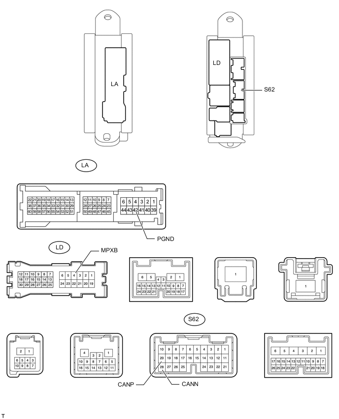
Terminal No. (Symbol) Wiring Color Switch Condition Specified Condition S62-20 (CANP) - S62-28 (CANN) B - W Power switch off 108 to 132 Ω S62-20 (CANP) - LA-43 (PGND) B - W-B Power switch off 200 Ω or higher S62-28 (CANN) - LA-43 (PGND) W - W-B Power switch off 200 Ω or higher S62-20 (CANP) - LD-4 (MPXB) B - R Power switch off 6 kΩ or higher S62-28 (CANN) - LD-4 (MPXB) W - R Power switch off 6 kΩ or higher
-
-
CHECK TIRE PRESSURE WARNING RECEIVER ASSEMBLY (w/ Tire Pressure Warning System)
-
Disconnect the tire pressure warning receiver assembly connector.
-
Measure the resistance according to the value(s) in the table below.
Terminal No. (Symbol) Wiring Color Switch Condition Specified Condition L175-3 (CANP) - L175-6 (CANN) B - W Power switch off 54 to 69 Ω L175-3 (CANP) - L175-4 (GND) B - W-B Power switch off 200 Ω or higher L175-6 (CANN) - L175-4 (GND) W - W-B Power switch off 200 Ω or higher L175-3 (CANP) - L31-16 (BAT) B - B Power switch off 6 kΩ or higher L175-6 (CANN) - L31-16 (BAT) W - B Power switch off 6 kΩ or higher
-
-
CHECK OPTION CONNECTOR (BUS BUFFER ECU) (w/ Bus Buffer ECU)
-
Disconnect the option connector (bus buffer ECU) connector.
-
Measure the resistance according to the value(s) in the table below.
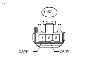
Terminal No. (Symbol) Wiring Color Switch Condition Specified Condition L157-1 (CANP) - L157-2 (CANN) B - W Power switch off 108 to 132 Ω
-
-
CHECK MILLIMETER WAVE RADAR SENSOR ASSEMBLY (w/ Pre-crash Safety System)
-
Disconnect the millimeter wave radar sensor assembly connector.
-
Measure the resistance according to the value(s) in the table below.
Terminal No. (Symbol) Wiring Color Switch Condition Specified Condition B9-4 (CA1P) - B9-3 (CA1N) B - L Power switch off 108 to 132 Ω B9-4 (CA1P) - L31-4 (CG) B - W-B Power switch off 200 Ω or higher B9-3 (CA1N) - L31-4 (CG) L - W-B Power switch off 200 Ω or higher B9-4 (CA1P) - L31-16 (BAT) B - B Power switch off 6 kΩ or higher B9-3 (CA1N) - L31-16 (BAT) L - B Power switch off 6 kΩ or higher
-
-
CHECK REAR MILLIMETER WAVE RADAR SENSOR ASSEMBLY (w/ Pre-crash Intelligent Headrest)

-
Disconnect the rear millimeter wave radar sensor assembly connector.
-
Measure the resistance according to the value(s) in the table below.
Terminal No. (Symbol) Wiring Color Switch Condition Specified Condition R51-4 (CA1P) - R51-3 (CA1N) B - W Power switch off 108 to 132 Ω R51-4 (CA1P) - L31-4 (CG) B - W-B Power switch off 200 Ω or higher R51-3 (CA1N) - L31-4 (CG) W - W-B Power switch off 200 Ω or higher R51-4 (CA1P) - L31-16 (BAT) B - B Power switch off 6 kΩ or higher R51-3 (CA1N) - L31-16 (BAT) W - B Power switch off 6 kΩ or higher
-
-
CHECK OBJECT RECOGNITION ECU (w/ Driver Monitor Camera)
-
Disconnect the object recognition ECU connector.
-
Measure the resistance according to the value(s) in the table below.
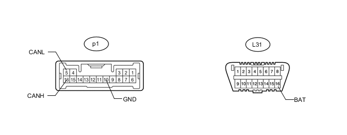
Terminal No. (Symbol) Wiring Color Switch Condition Specified Condition p1-16 (CANH) - p1-5 (CANL) B - W Power switch off 54 to 69 Ω p1-16 (CANH) - p1-10 (GND) B - W-B Power switch off 200 Ω or higher p1-5 (CANL) - p1-10 (GND) W - W-B Power switch off 200 Ω or higher p1-16 (CANH) - L31-16 (BAT) B - B Power switch off 6 kΩ or higher p1-5 (CANL) - L31-16 (BAT) W - B Power switch off 6 kΩ or higher
-
-
CHECK DRIVER MONITOR ECU ASSEMBLY (w/ Driver Monitor Camera)
-
Disconnect the driver monitor ECU assembly connector.
-
Measure the resistance according to the value(s) in the table below.
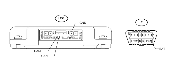
Terminal No. (Symbol) Wiring Color Switch Condition Specified Condition L158-12 (CANH) - L158-11 (CANL) B - W Power switch off 54 to 69 Ω L158-12 (CANH) - L158-2 (GND) B - B Power switch off 200 Ω or higher L158-11 (CANL) - L158-2 (GND) W - B Power switch off 200 Ω or higher L158-12 (CANH) - L31-16 (BAT) B - B Power switch off 6 kΩ or higher L158-11 (CANL) - L31-16 (BAT) W - B Power switch off 6 kΩ or higher
-
-
CHECK NO. 1 NIGHT VIEW ECU (w/ Night View System)
-
Disconnect the No. 1 night view ECU connector.
-
Measure the resistance according to the value(s) in the table below.
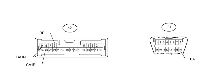
Terminal No. (Symbol) Wiring Color Switch Condition Specified Condition p2-8 (CA1P) - p2-9 (CA1N) Y - L Power switch off 54 to 69 Ω p2-8 (CA1P) - p2-6 (RE) Y - W-B Power switch off 200 Ω or higher p2-9 (CA1N) - p2-6 (RE) L - W-B Power switch off 200 Ω or higher p2-8 (CA1P) - L31-16 (BAT) Y - B Power switch off 6 kΩ or higher p2-9 (CA1N) - L31-16 (BAT) L - B Power switch off 6 kΩ or higher
-
-
CHECK ACTIVE HEADREST CONTROL ECU LH (FRONT SEAT HEADREST ASSEMBLY LH) (w/ Pre-crash Intelligent Headrest)
-
Disconnect the active headrest control ECU LH (front seat headrest assembly LH) connector.
-
Measure the resistance according to the value(s) in the table below.
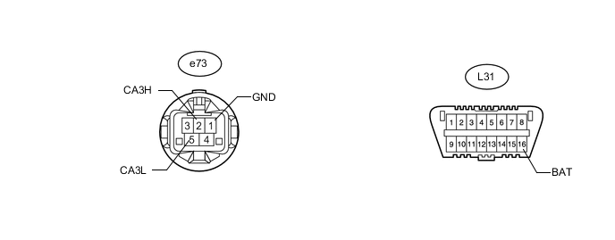
Terminal No. (Symbol) Wiring Color Switch Condition Specified Condition e73-2 (CA3H) - e73-5 (CA3L) R - G Power switch off 108 to 132 Ω e73-2 (CA3H) - e73-1 (GND) R - W-B Power switch off 200 Ω or higher e73-5 (CA3L) - e73-1 (GND) G - W-B Power switch off 200 Ω or higher e73-2 (CA3H) - L31-16 (BAT) R - B Power switch off 6 kΩ or higher e73-5 (CA3L) - L31-16 (BAT) G - B Power switch off 6 kΩ or higher
-
-
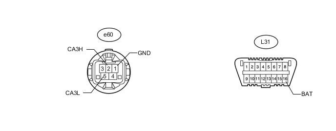
CHECK ACTIVE HEADREST CONTROL ECU RH (FRONT SEAT HEADREST ASSEMBLY RH) (w/ Pre-crash Intelligent Headrest [for 5-Passenger with Ottoman])
-
Disconnect the active headrest control ECU RH (front seat headrest assembly RH) connector.
-
Measure the resistance according to the value(s) in the table below.
Terminal No. (Symbol) Wiring Color Switch Condition Specified Condition e60-2 (CA3H) - e60-5 (CA3L) R - G Power switch off 108 to 132 Ω e60-2 (CA3H) - e60-1 (GND) R - W-B Power switch off 200 Ω or higher e60-5 (CA3L) - e60-1 (GND) G - W-B Power switch off 200 Ω or higher e60-2 (CA3H) - L31-16 (BAT) R - B Power switch off 6 kΩ or higher e60-5 (CA3L) - L31-16 (BAT) G - B Power switch off 6 kΩ or higher
-
-
CHECK TELEMATICS TRANSCEIVER (w/ Telematics Transceiver)

-
Disconnect the telematics transceiver connector.
-
Measure the resistance according to the value(s) in the table below.
Terminal No. (Symbol) Wiring Color Switch Condition Specified Condition L191-15 (CANP) - L191-16 (CANN) R - G Power switch off 54 to 69 Ω L191-15 (CANP) - L191-4 (E) R - W-B Power switch off 200 Ω or higher L191-16 (CANN) - L191-4 (E) G - W-B Power switch off 200 Ω or higher L191-15 (CANP) - L191-1 (+B) R - R Power switch off 6 kΩ or higher L191-16 (CANN) - L191-1 (+B) G - R Power switch off 6 kΩ or higher
-