LIN COMMUNICATION SYSTEM, Diagnostic DTC:U1127
| DTC Code | DTC Name |
|---|---|
| U1127 | Lost Communication with Center Console Switch ECU |
DESCRIPTION
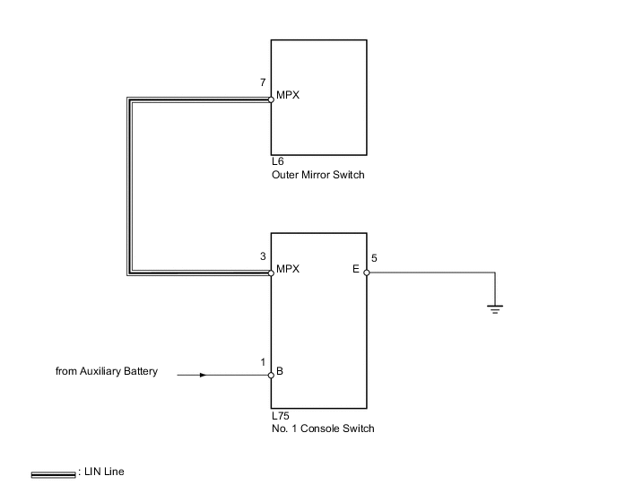
This DTC is output when LIN communication between the outer mirror switch and No. 1 console switch stops for 10 seconds or more.
| DTC Code | DTC Detection Condition | Trouble Area |
|---|---|---|
| U1127 | No communication between outer mirror switch and No. 1 console switch for 10 seconds or more |
|
WIRING DIAGRAM
CAUTION / NOTICE / HINT
Note
-
When using the intelligent tester with the power switch off to troubleshoot:
Connect the intelligent tester to the vehicle, and turn a courtesy switch on and off at 1.5 second intervals until communication between the tester and vehicle begins.
-
Inspect the fuses for circuits related to this system before performing the following inspection procedure.
Tech Tips
When DTC U1127, U1128 and U1129 are output simultaneously, perform troubleshooting for "Driver Side Switch Module LIN Communication Malfunction" first Click here.
PROCEDURE
-
CLEAR DTC
-
Clear the DTC Click here.
NEXT 
-
-
CHECK FOR DTC
-
Recheck for DTC Click here.
Result: Result Proceed to DTC U1127 output reoccurs A DTC U1127 output does not reoccur B
B 
USE SIMULATION METHOD TO CHECK Click here
A
-
-
CHECK HARNESS AND CONNECTOR (OUTER MIRROR SWITCH - NO. 1 CONSOLE SWITCH)
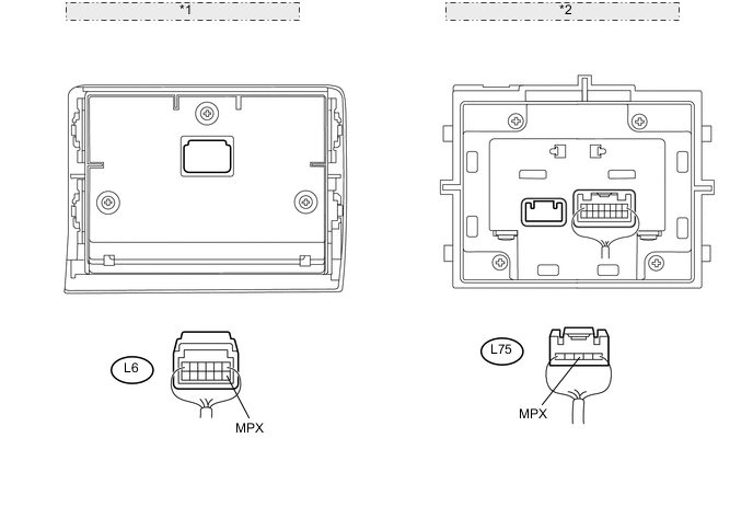
*1 Rear view of wire harness connector: (to Outer Mirror Switch) *2 Rear view of wire harness connector: (to No. 1 Console Switch)
-
Disconnect the L6 and L75 switch connectors.
-
Measure the resistance and voltage according to the value(s) in the table below.
Standard resistance Tester Connection Condition Specified Condition L6-7 (MPX) - L75-3 (MPX) Always Below 1 Ω L6-7 (MPX) or L75-3 (MPX) - Body ground Always 10 kΩ or higher Standard voltage Tester Connection Switch Condition Specified Condition L6-7 (MPX) or L75-3 (MPX) - Body ground Power switch on (IG) Below 1 V
NG
REPAIR OR REPLACE HARNESS OR CONNECTOR
OK
-
-
CHECK HARNESS AND CONNECTOR (NO. 1 CONSOLE SWITCH - BATTERY AND BODY GROUND)
-
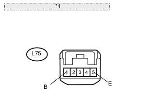
*1 Front view of wire harness connector: (to No. 1 Console Switch) Disconnect the L75 switch connector.
-
Measure the resistance and voltage according to the value(s) in the table below.
Standard resistance Tester Connection Condition Specified Condition L75-5 (E) - Body ground Always Below 1 Ω Standard voltage Tester Connection Condition Specified Condition L75-1 (B) - Body ground Always 11 to 14 V
NG
REPAIR OR REPLACE HARNESS OR CONNECTOR
OK
-
-
CHECK NO. 1 CONSOLE SWITCH (OPERATION)
-
Temporarily replace the No. 1 console switch with a new or normally functioning one.
-
Clear the DTC Click here.
NEXT
-
-
CHECK FOR DTC
-
Recheck for DTC Click here.
Result: Result Proceed to DTC U1127 output does not reoccur A DTC U1127 output reoccurs B
A
END (NO. 1 CONSOLE SWITCH IS DEFECTIVE)
B
REPLACE OUTER MIRROR SWITCH Click here
-