LIN COMMUNICATION SYSTEM TERMINALS OF ECU
-
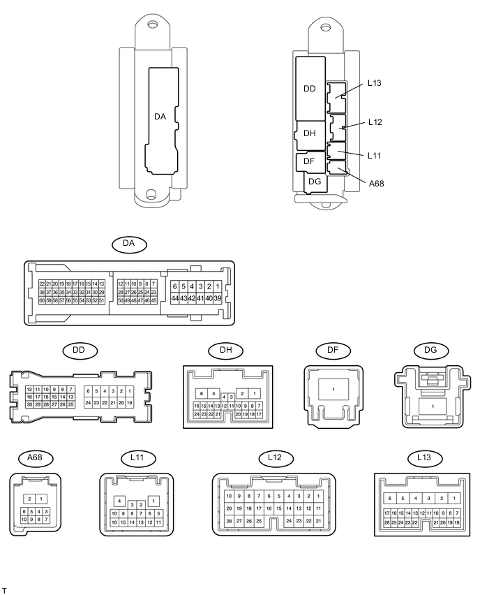
CHECK MAIN BODY ECU (DRIVER SIDE JUNCTION BLOCK)
-
Disconnect the DA, L12 and L13 ECU connectors.
-
Measure the resistance and voltage according to the value(s) in the table below.
Terminal No. (Symbols) Wiring Color Terminal Description Condition Specified Condition DA-40 (GND1) - Body ground W-B - Body ground Ground Always Below 1 Ω DA-40 (GND2) - Body ground W-B - Body ground Ground Always Below 1 Ω L12-1 (AM2) - DA-40 (GND2) W - W-B Battery power supply Always 11 to 14 V L13-6 (AM1) - DA-40 (GND2) W - W-B Battery power supply Always 11 to 14 V If the result is not as specified, there may be a malfunction on the wire harness side.
-
-
CHECK MASTER SWITCH ASSEMBLY

-
Disconnect the N13 master switch connector.
-
Measure the voltage and resistance according to the value(s) in the table below.
Terminal No. (Symbols) Wiring Color Terminal Description Condition Specified Condition N13-11 (B) - N13-12 (GND) B - R Battery power supply Always 11 to 14 V N13-12 (GND) - Body ground R - Body ground Ground Always Below 1 Ω If the result is not as specified, there may be a malfunction on the wire harness side.
-
-
CHECK POWER WINDOW REGULATOR MOTOR ASSEMBLY (for Driver Side)

-
Disconnect the N11*1 or N3*2 motor connector.
-
*1: for LHD
-
*2: for RHD
-
-
Measure the voltage and resistance according to the value(s) in the table below.
for LHD Terminal No. (Symbols) Wiring Color Terminal Description Condition Specified Condition N11-2 (B) - N11-1 (E) BE - B Battery power supply Always 11 to 14 V N11-1 (E) - Body ground B - Body ground Ground Always Below 1 Ω for RHD Terminal No. (Symbols) Wiring Color Terminal Description Condition Specified Condition N3-2 (B) - N3-1 (E) BE - B Battery power supply Always 11 to 14 V N3-1 (E) - Body ground B - Body ground Ground Always Below 1 Ω If the result is not as specified, there may be a malfunction on the wire harness side.
-
-
CHECK POWER WINDOW REGULATOR MOTOR ASSEMBLY (for Front Passenger Side)

-
Disconnect the N3*1 or N11*2 motor connector.
-
*1: for LHD
-
*2: for RHD
-
-
Measure the voltage and resistance according to the value(s) in the table below.
for LHD Terminal No. (Symbols) Wiring Color Terminal Description Condition Specified Condition N3-2 (B) - N3-1 (E) BE - B Battery power supply Always 11 to 14 V N3-1 (E) - Body ground B - Body ground Ground Always Below 1 Ω for RHD Terminal No. (Symbols) Wiring Color Terminal Description Condition Specified Condition N11-2 (B) - N11-1 (E) BE - B Battery power supply Always 11 to 14 V N11-1 (E) - Body ground B - Body ground Ground Always Below 1 Ω If the result is not as specified, there may be a malfunction on the wire harness side.
-
-
CHECK REAR POWER WINDOW REGULATOR MOTOR ASSEMBLY LH

-
Disconnect the O19 motor connector.
-
Measure the voltage and resistance according to the value(s) in the table below.
Terminal No. (Symbols) Wiring Color Terminal Description Condition Specified Condition O19-2 (B) - O19-1 (E) BE - B Battery power supply Always 11 to 14 V O19-1 (E) - Body ground B - Body ground Ground Always Below 1 Ω If the result is not as specified, there may be a malfunction on the wire harness side.
-
-
CHECK REAR POWER WINDOW REGULATOR MOTOR ASSEMBLY RH

-
Disconnect the O8 motor connector.
-
Measure the voltage and resistance according to the value(s) in the table below.
Terminal No. (Symbols) Wiring Color Terminal Description Condition Specified Condition O8-2 (B) - O8-1 (E) BE - B Battery power supply Always 11 to 14 V O8-1 (E) - Body ground B - Body ground Ground Always Below 1 Ω If the result is not as specified, there may be a malfunction on the wire harness side.
-
-
CHECK SLIDING ROOF DRIVE GEAR SUB-ASSEMBLY (SLIDING ROOF ECU) (w/ Sliding Roof System)

-
Disconnect the X5 ECU connector.
-
Measure the voltage and resistance according to the value(s) in the table below.
Terminal No. (Symbols) Wiring Color Terminal Description Condition Specified Condition X5-1 (B) - X5-2 (E) B - W-B Battery power supply Always 11 to 14 V X5-2 (E) - Body ground W-B - Body ground Ground Always Below 1 Ω If the result is not as specified, there may be a malfunction on the wire harness side.
-
-
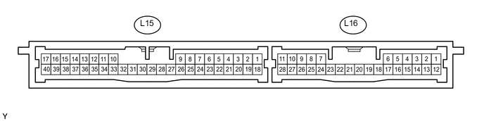
CHECK CERTIFICATION ECU
-
Disconnect the L15 ECU connector.
-
Measure the voltage and resistance according to the value(s) in the table below.
Terminal No. (Symbols) Wiring Color Terminal Description Condition Specified Condition L15-1 (+B1) - L15-17 (E) L - W-B Battery power supply Always 11 to 14 V L15-17 (E) - Body ground W-B - Body ground Ground Always Below 1 Ω If the result is not as specified, there may be a malfunction on the wire harness side.
-
-
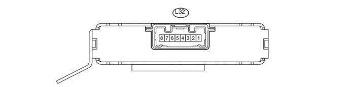
CHECK ID CODE BOX
-
Disconnect the L32 ECU connector.
-
Measure the voltage and resistance according to the value(s) in the table below.
Terminal No. (Symbols) Wiring Color Terminal Description Condition Specified Condition L32-1 (+B) - L32-8 (GND) L - W-B Battery power supply Always 11 to 14 V L32-8 (GND) - Body ground W-B - Body ground Ground Always Below 1 Ω If the result is not as specified, there may be a malfunction on the wire harness side.
-
-
CHECK STEERING LOCK ACTUATOR ASSEMBLY (STEERING LOCK ECU)

-
Disconnect the L33 ECU connector.
-
Measure the voltage and resistance according to the value(s) in the table below.
Terminal No. (Symbols) Wiring Color Terminal Description Condition Specified Condition L33-7 (B) - L33-1 (GND) P - W-B Battery power supply Always 11 to 14 V L33-1 (GND) - Body ground W-B - Body ground Ground Always Below 1 Ω If the result is not as specified, there may be a malfunction on the wire harness side.
-
-
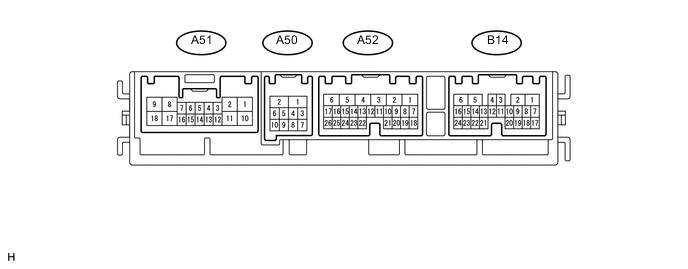
CHECK MULTIPLEX NETWORK FRONT LIGHT ECU (FRONT CONTROLLER)
-
Disconnect the A50 ECU connector.
-
Measure the voltage and resistance according to the value(s) in the table below.
Terminal No. (Symbols) Wiring Color Terminal Description Condition Specified Condition A50-1 (FMB3) - A50-2 (E) LG - W-B Battery power supply Always 11 to 14 V A50-5 (FMIG) - A50-2 (E) Y - W-B IG power supply Power switch off Below 1 V A50-5 (FMIG) - A50-2 (E) Y - W-B IG power supply Power switch on (IG) 11 to 14 V A50-2 (E) - Body ground W-B - Body ground Ground Always Below 1 Ω If the result is not as specified, there may be a malfunction on the wire harness side.
-
-
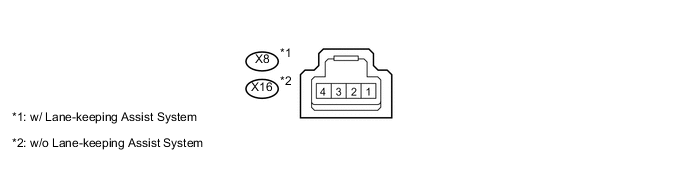
CHECK RAIN SENSOR
-
Disconnect the X8*1 or X16*2 sensor connector.
-
*1: w/ Lane-keeping Assist System
-
*2: w/o Lane-keeping Assist System
-
-
Measure the voltage and resistance according to the value(s) in the table below.
w/ Lane-keeping Assist System Terminal No. (Symbols) Wiring Color Terminal Description Condition Specified Condition X8-4 (SIG) - X8-1 (ES) LG- BR IG power supply Power switch off Below 1 V X8-4 (SIG) - X8-1 (ES) LG- BR IG power supply Power switch on (IG) 11 to 14 V X8-1 (ES) - Body ground BR - Body ground Ground Always Below 1 Ω w/o Lane-keeping Assist System Terminal No. (Symbols) Wiring Color Terminal Description Condition Specified Condition X16-4 (SIG) - X16-1 (ES) LG- BR IG power supply Power switch off Below 1 V X16-4 (SIG) - X16-1 (ES) LG- BR IG power supply Power switch on (IG) 11 to 14 V X16-1 (ES) - Body ground BR - Body ground Ground Always Below 1 Ω If the result is not as specified, there may be a malfunction on the wire harness side.
-
-
CHECK LUGGAGE ROOM JUNCTION BLOCK ASSEMBLY (REAR JUNCTION BLOCK ECU)

*1 LF
-
Disconnect the LA and LD ECU connectors.
-
Measure the voltage and resistance according to the value(s) in the table below.
Terminal No. (Symbols) Wiring Color Terminal Description Condition Specified Condition LD-4 (MPXB) - LA-29 (SG) R - W-B Battery power supply Always 11 to 14 V LA-29 (SG) - Body ground W-B - Body ground Ground Always Below 1 Ω If the result is not as specified, there may be a malfunction on the wire harness side.
-
-
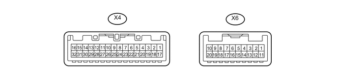
CHECK MAP LIGHT ASSEMBLY (OVERHEAD JUNCTION BLOCK)
-
Disconnect the X4 and X6 ECU connectors.
-
Measure the voltage and resistance according to the value(s) in the table below.
Terminal No. (Symbols) Wiring Color Terminal Description Condition Specified Condition X4-6 (+B) - X4-16 (GND9) B - W-B Battery power supply Always 11 to 14 V X4-16 (GND9) - Body ground W-B - Body ground Ground Always Below 1 Ω If the result is not as specified, there may be a malfunction on the wire harness side.
-
-
CHECK OUTER MIRROR SWITCH

-
Disconnect the L6 switch connector.
-
Measure the voltage and resistance according to the value(s) in the table below.
Terminal No. (Symbols) Wiring Color Terminal Description Condition Specified Condition L6-1 (E) - Body ground W-B - Body ground Ground Always Below 1 Ω L6-11 (IG) - L6-1 (E) G - W-B IG power supply Power switch off Below 1 V L6-11 (IG) - L6-1 (E) G - W-B IG power supply Power switch on (IG) 11 to 14 V L6-12 (B) - L6-1 (E) B - W-B Battery power supply Always 11 to 14 V If the result is not as specified, there may be a malfunction on the wire harness side.
-
-
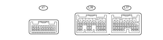
CHECK NO. 1 CONSOLE SWITCH

-
Disconnect the L75 switch connector.
-
Measure the voltage and resistance according to the value(s) in the table below.
Terminal No. (Symbols) Wiring Color Terminal Description Condition Specified Condition L75-1 (B) - L75-5 (E) B - W-B Battery power supply Always 11 to 14 V L75-5 (E) - Body ground W-B - Body ground Ground Always Below 1 Ω If the result is not as specified, there may be a malfunction on the wire harness side.
-
-
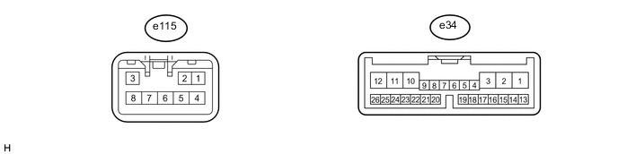
CHECK FRONT SEAT CLIMATE CONTROL ECU LH
-
Disconnect the e34 ECU connector.
-
Measure the voltage and resistance according to the value(s) in the table below.
Terminal No. (Symbols) Wiring Color Terminal Description Condition Specified Condition e34-1 (IG) - e34-12 (GND) P - W-B IG power supply Power switch off Below 1 V e34-1 (IG) - e34-12 (GND) P - W-B IG power supply Power switch on (IG) 11 to 14 V e34-2 (SYSB) - e34-12 (GND) R - W-B Battery power supply Always 11 to 14 V e34-12 (GND) - Body ground W-B - Body ground Ground Always Below 1 Ω If the result is not as specified, there may be a malfunction on the wire harness side.
-
-
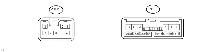
CHECK FRONT SEAT CLIMATE CONTROL ECU RH
-
Disconnect the e4 ECU connector.
-
Measure the voltage and resistance according to the value(s) in the table below.
for LHD Terminal No. (Symbols) Wiring Color Terminal Description Condition Specified Condition e4-1 (IG) - e4-12 (GND) Y - W-B IG power supply Power switch off Below 1 V e4-1 (IG) - e4-12 (GND) Y - W-B IG power supply Power switch on (IG) 11 to 14 V e4-2 (SYSB) - e4-12 (GND) W - W-B Battery power supply Always 11 to 14 V e4-11 (VER) - Body ground W-B - Body ground Ground Always Below 1 Ω e4-12 (GND) - Body ground W-B - Body ground Ground Always Below 1 Ω for RHD Terminal No. (Symbols) Wiring Color Terminal Description Condition Specified Condition e4-1 (IG) - e4-12 (GND) GR - W-B IG power supply Power switch off Below 1 V e4-1 (IG) - e4-12 (GND) GR - W-B IG power supply Power switch on (IG) 11 to 14 V e4-2 (SYSB) - e4-12 (GND) W - W-B Battery power supply Always 11 to 14 V e4-11 (VER) - Body ground W-B - Body ground Ground Always Below 1 Ω e4-12 (GND) - Body ground W-B - Body ground Ground Always Below 1 Ω If the result is not as specified, there may be a malfunction on the wire harness side.
-
-
CHECK AIR CONDITIONING AMPLIFIER ASSEMBLY (A/C ECU)
-
Disconnect the L76 ECU connector.
-
Measure the voltage and resistance according to the value(s) in the table below.
Terminal No. (Symbols) Wiring Color Terminal Description Condition Specified Condition L76-5 (IG+) - L76-1 (GND) V - W-B IG power supply Power switch off Below 1 V L76-5 (IG+) - L76-1 (GND) V - W-B IG power supply Power switch on (IG) 11 to 14 V L76-6 (+B1) - L76-1 (GND) L - W-B Battery power supply Always 11 to 14 V L76-7 (+B2) - L76-1 (GND) L - W-B Battery power supply Always 11 to 14 V L76-1 (GND) - Body ground W-B - Body ground Ground Always Below 1 Ω If the result is not as specified, there may be a malfunction on the wire harness side.
-
-
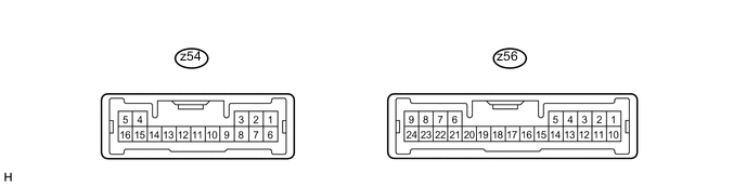
CHECK REAR POWER SEAT MODULE SWITCH (except 4-Passenger with Ottoman)
-
Disconnect the z54 switch connector.
-
Measure the voltage and resistance according to the value(s) in the table below.
Terminal No. (Symbols) Wiring Color Terminal Description Condition Specified Condition z54-14 (B) - z54-9 (E) W - W-B Battery power supply Always 11 to 14 V z54-9 (E) - Body ground W-B - Body ground Ground Always Below 1 Ω If the result is not as specified, there may be a malfunction on the wire harness side.
-
-
CHECK REAR POWER SEAT MODULE SWITCH (for 4-Passenger with Ottoman)

-
Disconnect the S15 switch connector.
-
Measure the voltage and resistance according to the value(s) in the table below.
Terminal No. (Symbols) Wiring Color Terminal Description Condition Specified Condition S15-6 (B) - S15-1 (E) W - W-B Battery power supply Always 11 to 14 V S15-1 (E) - Body ground W-B - Body ground Ground Always Below 1 Ω If the result is not as specified, there may be a malfunction on the wire harness side.
-
-
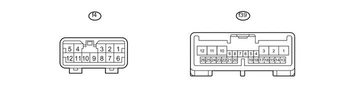
CHECK POSITION CONTROL ECU RH (w/ Rear Power Seat Control System)
-
Disconnect the f4 and f39 ECU connectors.
-
Measure the voltage and resistance according to the value(s) in the table below.
Terminal No. (Symbols) Wiring Color Terminal Description Condition Specified Condition f4-1 (+B) - f4-6 (GND) L - W-B Battery power supply Always 11 to 14 V f39-16 (SYSB) - f4-6 (GND) R - W-B Battery power supply Always 11 to 14 V f39-26 (SEL) - f39-25 (SEL2) B - B Right or left identification Always Below 1 Ω If the result is not as specified, there may be a malfunction on the wire harness side.
-
-
CHECK POSITION CONTROL ECU LH (w/ Rear Power Seat Control System)

-
Disconnect the f24 and f43 ECU connectors.
-
Measure the voltage and resistance according to the value(s) in the table below.
Terminal No. (Symbols) Wiring Color Terminal Description Condition Specified Condition f24-1 (+B) - f24-6 (GND) L - W-B Battery power supply Always 11 to 14 V f43-16 (SYSB) - f24-6 (GND) R - W-B Battery power supply Always 11 to 14 V f43-23 (SGND) - Body ground W-B - Body ground Ground Always Below 1 Ω If the result is not as specified, there may be a malfunction on the wire harness side.
-
-
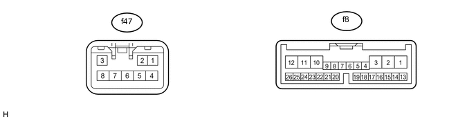
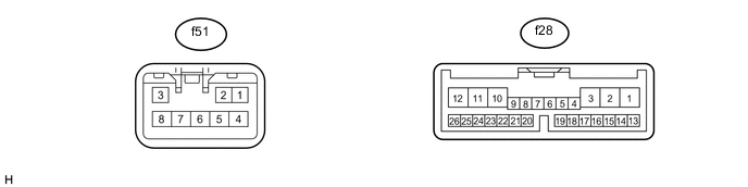
CHECK REAR SEAT CLIMATE CONTROL ECU RH (w/ Climate Control Seat System)
-
Disconnect the f8 ECU connector.
-
Measure the voltage and resistance according to the value(s) in the table below.
Terminal No. (Symbols) Wiring Color Terminal Description Condition Specified Condition f8-1 (IG) - f8-12 (GND) Y - W-B IG power supply Power switch off Below 1 V f8-1 (IG) - f8-12 (GND) Y - W-B IG power supply Power switch on (IG) 11 to 14 V f8-2 (SYSB) - f8-12 (GND) G - W-B Battery power supply Always 11 to 14 V f8-11 (VER) - Body ground W-B - Body ground Ground Always Below 1 Ω f8-12 (GND) - Body ground W-B - Body ground Ground Always Below 1 Ω If the result is not as specified, there may be a malfunction on the wire harness side.
-
-
CHECK REAR SEAT CLIMATE CONTROL ECU LH (w/ Climate Control Seat System)
-
Disconnect the f28 ECU connector.
-
Measure the voltage and resistance according to the value(s) in the table below.
Terminal No. (Symbols) Wiring Color Terminal Description Condition Specified Condition f28-1 (IG) - f28-12 (GND) P - W-B IG power supply Power switch off Below 1 V f28-1 (IG) - f28-12 (GND) P - W-B IG power supply Power switch on (IG) 11 to 14 V f28-2 (SYSB) - f28-12 (GND) V - W-B Battery power supply Always 11 to 14 V f28-12 (GND) - Body ground W-B - Body ground Ground Always Below 1 Ω If the result is not as specified, there may be a malfunction on the wire harness side.
-
-
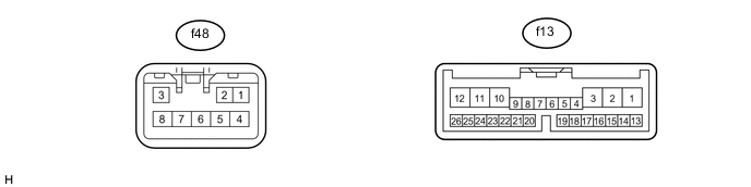
CHECK REAR SEAT CLIMATE CONTROL ECU LH (w/ Seat Heater System)
-
Disconnect the f13 ECU connector.
-
Measure the voltage and resistance according to the value(s) in the table below.
Terminal No. (Symbols) Wiring Color Terminal Description Condition Specified Condition f13-1 (AMP) - f13-12 (GND) L - W-B IG power supply Power switch off Below 1 V f13-1 (AMP) - f13-12 (GND) L - W-B IG power supply Power switch on (IG) 11 to 14 V f13-2 (SYSB) - f13-12 (GND) G - W-B Battery power supply Always 11 to 14 V f13-12 (GND) - Body ground W-B - Body ground Ground Always Below 1 Ω If the result is not as specified, there may be a malfunction on the wire harness side.
-
-
CHECK SEAT VIBRATOR MODULE ASSEMBLY (w/ Seat Vibration System [for Ottoman])

-
Disconnect the S29 module connector.
-
Measure the voltage and resistance according to the value(s) in the table below.
Terminal No. (Symbols) Wiring Color Terminal Description Condition Specified Condition S29-1 (IG) - S29-8 (GND) BR - W-B IG power supply Power switch off Below 1 V S29-1 (IG) - S29-8 (GND) BR - W-B IG power supply Power switch on (IG) 11 to 14 V S29-8 (GND) - Body ground W-B - Body ground Ground Always Below 1 Ω If the result is not as specified, there may be a malfunction on the wire harness side.
-