PARKING ASSIST MONITOR SYSTEM SYSTEM DESCRIPTION
-
GENERAL
-
This system has a television camera assembly mounted on the back door to display the rear view of the vehicle on the accessory meter assembly. The display panel also shows a composite view consisting of the area behind the vehicle and parking guidelines to assist the driver in parking the vehicle by monitoring the area behind the vehicle.
-
This system consists of the following components:
-
Multi-media module receiver assembly
-
Television camera assembly
-
Accessory meter assembly
-
Main body ECU (driver side junction block assembly)
-
Steering sensor
-
Luggage room junction block assembly (rear junction block ECU)
-
Clearance warning ECU assembly
-
Steering control ECU
-
Headlight swivel ECU
-
-
This system is equipped with a self-diagnosis system, which is operated from a designated window that appears on the display panel, just as in the audio and visual system.
-
-
FUNCTION OF COMPONENTS
-
The multi-media module receiver assembly controls the system by using information from the following components.
Item Function Multi-media Module Receiver Assembly
-
Receives video signals, which contain an image of the area behind the vehicle taken with the television camera assembly.
-
Performs overall control of the system by receiving signals from the sensors.
-
Allows operation via the remote touch when the park assist monitor screen or diagnosis screen is displayed.
-
Creates images and displays adjustment screens performed on the diagnosis screen.
-
Stops displaying the guide line and buttons displays "Check surrounding for safety" when an open signal is received for the luggage compartment door.
-
Displays "Back door is open" on the back camera position setting screen when an open signal is received for the luggage compartment door.
-
Performs control of the system by receiving the reverse signal from the ECM.
Television Camera Assembly
-
Mounted on the back door to transmit an image of the area behind the vehicle to the multi-media module receiver assembly.
-
Has a color video camera that uses a Complementary Metal Oxide Semiconductor (CMOS) and a wide-angle lens.
Accessory Meter Assembly Receives the video signals containing a composite of an image of the area behind the vehicle and parking assist guideline signals from the multi-media module receiver assembly, and displays them on the display panel. Main Body ECU (Driver Side Junction Block Assembly) Sends the courtesy light switch signal to multi-media module receiver assembly through CAN communication. Steering Sensor Detects the angle of the steering wheel and sends the resulting signals to the multi-media module receiver assembly through CAN communication. Combination Meter Assembly Sends a vehicle speed signal to the multi-media module receiver assembly. Clearance Warning ECU Assembly Sends a clearance detection data signal to the multi-media module receiver assembly through CAN communication. Luggage Room Junction Block Assembly (Rear Junction Block ECU) Sends a reverse signal to the multi-media module receiver assembly. Steering Control ECU Sends a VGRS relative angle signal to the multi-media module receiver assembly through CAN communication. Headlight Swivel ECU Sends a wheel base information signal to the multi-media module receiver assembly. -
-
-
OPERATION EXPLANATION
-
The reverse signal is sent to the multi-media module receiver assembly when the shift lever is moved to R.
After receiving the reverse position signal, the multi-media module receiver assembly switches the display signal for the accessory meter assembly from the audio and visual system to the parking assist monitor system.
-
In parallel parking assist mode, appropriate steering angle and timing information can be provided for the driver. This is based on the information from the steering angle sensor signal and the vehicle angle data signal that are sent to the multi-media module receiver assembly.
Tech Tips
The steering angle sensor signal is used to control parking assist only for estimated guide line mode.
-
-
DISPLAY MODE SETTING
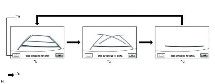
Text in Illustration *a Display Mode Switch Screen Button *b Estimated Course Line Display Mode *c Parking Assist Guide Line Display Mode *d Distance Guide Line Display Mode *e Display Mode Switch Screen Button Pressed - -
-
While the parking assist monitor is displayed, pressing the line mode button switches the parking assist monitor display mode.
Parking Assist Monitor Display Mode Parking Assist Monitor Display Mode Distance Guide Line
(Red)
Vehicle Width Extension Guide Line
(Blue)
Estimated Course Lines
(Yellow)
Parking Guide Line
(Blue)
Estimated Course Line Display Mode Displayed Displayed Displayed Not displayed Parking Assist Guide Line Display Mode Displayed Displayed Not displayed Displayed Distance Guide Line Display Mode Displayed Not displayed Not displayed Not displayed
-
-
DIAGNOSTIC FUNCTION OUTLINE
-
This parking assist monitor system has a diagnostic function displayed in the multi-media module receiver assembly. This function enables calibration (adjustment and verify) of the parking assist monitor system Click here.
-
The following items for the parking assist monitor system can be checked using the GTS.
Item Proceed to DTC
-