TELEMATICS TRANSCEIVER REMOVAL
CAUTION / NOTICE / HINT
Tech Tips
-
Use the same procedure for RHD and LHD vehicles.
-
The procedure listed below is for LHD vehicles.
PROCEDURE
-
PRECAUTION
CAUTION:
After turning the power switch off, waiting time may be required before disconnecting the cable from the auxiliary battery negative (-) terminal. Therefore, make sure to read the disconnecting the cable from the auxiliary battery negative (-) terminal notices before proceeding with work Click here.
Note
-
When replacing the multi-media module receiver assembly or telematics transceiver, perform the vehicle contract setting Click here.
-
The safety connect device uses the telematics transceiver to provide access to the network service.
-
The telematics transceiver has a DCM ID (described on the label attached to the telematics transceiver.
-
-
REMOVE LUGGAGE COMPARTMENT MAT SUB-ASSEMBLY (w/ Spare Tire)
-
REMOVE DECK BOARD ASSEMBLY (w/o Spare Tire)
-
REMOVE DECK TRIM SIDE BOARD LH (w/o Spare Tire)
-
REMOVE BATTERY SERVICE HOLE COVER LH
-
DISCONNECT CABLE FROM NEGATIVE AUXILIARY BATTERY TERMINAL
CAUTION:
Wait at least 90 seconds after disconnecting the cable from the auxiliary battery negative (-) terminal to disable the SRS system.
Note
When disconnecting the cable, some systems need to be initialized after the cable is reconnected Click here.
-
REMOVE INSTRUMENT PANEL FINISH PANEL END RH
-
REMOVE INSTRUMENT SIDE PANEL RH
-
REMOVE NO. 2 INSTRUMENT PANEL UNDER COVER SUB-ASSEMBLY
-
REMOVE LOWER INSTRUMENT PANEL
-
REMOVE FRONT PASSENGER SIDE KNEE AIRBAG ASSEMBLY
-
REMOVE GLOVE COMPARTMENT DOOR ASSEMBLY
-
REMOVE TELEMATICS TRANSCEIVER
-
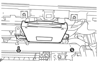
Remove the bolt and nut.
-
Disconnect each connector and remove the telematics transceiver.
-
-
REMOVE NO. 1 TELEPHONE BRACKET
-
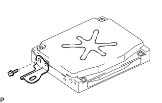
Remove the bolt and No. 1 telephone bracket.
-
-
REMOVE NO. 2 TELEPHONE BRACKET
-
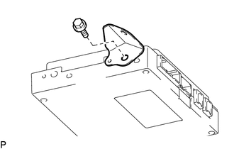
Remove the bolt and No. 2 telephone bracket.
-