PARKING ASSIST MONITOR SYSTEM Reverse Signal Circuit
DESCRIPTION
The multi-media module receiver assembly receives a reverse signal from the luggage room junction block assembly.
WIRING DIAGRAM
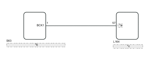
| *a | REV |
| *b | Luggage Room Junction Block Assembly (Rear Junction Block ECU) |
| *c | Multi-media Module Receiver Assembly |
PROCEDURE
-
CHECK MULTI-MEDIA MODULE RECEIVER ASSEMBLY (REVERSE SIGNAL)
-
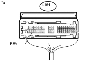
Text in Illustration *a Component with harness connected
(Multi-media Module Receiver Assembly)
Measure the voltage according to the value(s) in the table below.
Standard Voltage Tester Connection Switch Condition Specified Condition L164-57 (REV) - Body ground Power switch on (IG), shift lever in R 11 to 14 V L164-57 (REV) - Body ground Power switch on (IG), shift lever not in R Below 1 V
OK 
PROCEED TO NEXT SUSPECTED AREA SHOWN IN PROBLEM SYMPTOMS TABLE Click here
NG 
-
-
CHECK HARNESS AND CONNECTOR (MULTI-MEDIA MODULE RECEIVER ASSEMBLY - LUGGAGE ROOM JUNCTION BLOCK ASSEMBLY)
-
Disconnect the L164 multi-media module receiver assembly connector.
-
Disconnect the S63 luggage room junction block assembly connector.
-
Measure the resistance according to the value(s) in the table below.
Standard Resistance Tester Connection Condition Specified Condition L164-57 (REV) - S63-1 (BCK1) Always Below 1 Ω L164-57 (REV) - Body ground Always 10 kΩ or higher
OK
REPLACE LUGGAGE ROOM JUNCTION BLOCK ASSEMBLY (REAR JUNCTION BLOCK ECU)
NG
REPAIR OR REPLACE HARNESS OR CONNECTOR
-