MULTI-DISPLAY REMOVAL
PROCEDURE
-
PRECAUTION
CAUTION:
After turning the power switch off, waiting time may be required before disconnecting the cable from the auxiliary battery negative (-) terminal. Therefore, make sure to read the disconnecting the cable from the auxiliary battery negative (-) terminal notices before proceeding with work Click here.
-
REMOVE LUGGAGE COMPARTMENT MAT SUB-ASSEMBLY (w/ Spare Tire)
-
REMOVE DECK BOARD ASSEMBLY (w/o Spare Tire)
-
REMOVE DECK TRIM SIDE BOARD LH (w/o Spare Tire)
-
REMOVE BATTERY SERVICE HOLE COVER LH
-
DISCONNECT CABLE FROM NEGATIVE AUXILIARY BATTERY TERMINAL
Note
When disconnecting the cable, some systems need to be initialized after the cable is reconnected Click here.
-
REMOVE INSTRUMENT PANEL FINISH PANEL END LH
-
REMOVE INSTRUMENT PANEL FINISH PANEL END RH
-
REMOVE SHIFT LEVER KNOB SUB-ASSEMBLY
-
REMOVE NO. 3 BOX PANEL
-
REMOVE UPPER REAR CONSOLE PANEL SUB-ASSEMBLY
-
REMOVE UPPER INSTRUMENT CLUSTER FINISH PANEL
-
REMOVE UPPER CONSOLE PANEL SUB-ASSEMBLY
-
REMOVE LOWER NO. 1 INSTRUMENT PANEL FINISH PANEL
-
REMOVE LOWER NO. 2 INSTRUMENT PANEL FINISH PANEL
-
REMOVE MULTI-MEDIA MODULE RECEIVER ASSEMBLY
-
REMOVE INSTRUMENT CLUSTER FINISH PANEL GARNISH ASSEMBLY
-
REMOVE INSTRUMENT PANEL FINISH PANEL SUB-ASSEMBLY
-
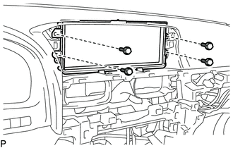
REMOVE ACCESSORY METER ASSEMBLY
-
Remove the 4 bolts.
-
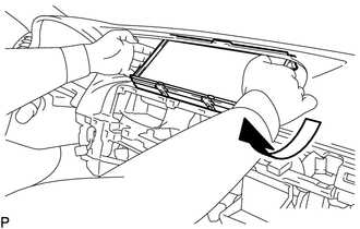
Move the accessory meter assembly in the direction of the arrow in the illustration.
-
Disconnect all the connectors and detach the clamp.
-
Remove the accessory meter assembly.
-
-
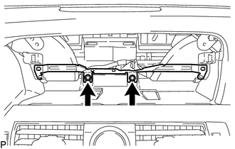
REMOVE NO. 1 COMBINATION METER BRACKET
-
Remove the 2 bolts and accessory meter bracket.
-