REAR SEAT ENTERTAINMENT SYSTEM Multi-display Controller Power Source Circuit
DESCRIPTION
This is power source circuit of the multi-display controller sub-assembly.
WIRING DIAGRAM
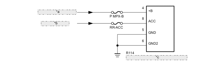
| *a | from Auxiliary Battery |
| *b | from RR-ACC Relay |
| *c | Multi-display Controller Sub-assembly |
PROCEDURE
-
CHECK HARNESS AND CONNECTOR (MULTI-DISPLAY CONTROLLER SUB-ASSEMBLY - BATTERY AND BODY GROUND)
-
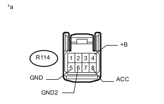
Text in Illustration *a Front view of wire harness connector
(to Multi-display Controller Sub-assembly)
Disconnect the multi-display controller sub-assembly connector.
-
Measure the resistance according to the value(s) in the table below.
Standard Resistance Tester Connection Condition Specified Condition R114-5 (GND) - Body ground Always Below 1 Ω R114-6 (GND2) - Body ground Always Below 1 Ω -
Measure the voltage according to the value(s) in the table below.
Standard Voltage Tester Connection Switch Condition Specified Condition R114-4 (+B) - Body ground Power switch off 11 to 14 V R114-8 (ACC) - Body ground Power switch on (ACC) 11 to 14 V
OK 
PROCEED TO NEXT SUSPECTED AREA SHOWN IN PROBLEM SYMPTOMS TABLE Click here
NG
REPAIR OR REPLACE HARNESS OR CONNECTOR
-