REAR SEAT ENTERTAINMENT SYSTEM Sound Signal Circuit between Multi-display Controller and Television Display
DESCRIPTION
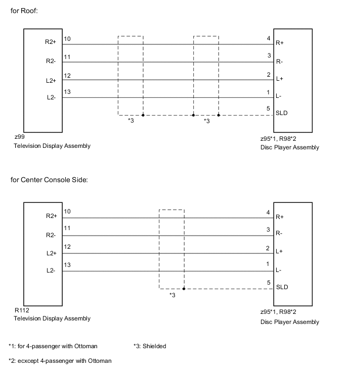
This is the sound signal circuit between the disc player assembly and the television display assembly.
WIRING DIAGRAM
PROCEDURE
-
CHECK HARNESS AND CONNECTOR (DISC PLAYER ASSEMBLY - TELEVISION DISPLAY ASSEMBLY)
-
*1: for 4-passenger with Ottoman
-
*2: except 4-passenger with Ottoman
-
for Roof:
-
Disconnect the z95*1 or R98*2 disc player assembly connector.
-
Disconnect the z99 television display assembly connector.
-
Measure the resistance according to the value(s) in the table below.
Standard Resistance for 4-passenger with Ottoman Tester Connection Condition Specified Condition z95-2 (L+) - z99-12 (L2+) Always Below 1 Ω z95-1 (L-) - z99-13 (L2-) Always Below 1 Ω z95-4 (R+) - z99-10 (R2+) Always Below 1 Ω z95-3 (R-) - z99-11 (R2-) Always Below 1 Ω z95-2 (L+) or z99-12 (L2+) - Body ground Always 10 kΩ or higher z95-1 (L-) or z99-13 (L2-) - Body ground Always 10 kΩ or higher z95-4 (R+) or z99-10 (R2+) - Body ground Always 10 kΩ or higher z95-3 (R-) or z99-11 (R2-) - Body ground Always 10 kΩ or higher z95-5 (SLD) - Body ground Always 10 kΩ or higher except 4-passenger with Ottoman Tester Connection Condition Specified Condition R98-2 (L+) - z99-12 (L2+) Always Below 1 Ω R98-1 (L-) - z99-13 (L2-) Always Below 1 Ω R98-4 (R+) - z99-10 (R2+) Always Below 1 Ω R98-3 (R-) - z99-11 (R2-) Always Below 1 Ω R98-2 (L+) - z99-12 (L2+) - Body ground Always 10 kΩ or higher R98-1 (L-) or z99-13 (L2-) - Body ground Always 10 kΩ or higher R98-4 (R+) or z99-10 (R2+) - Body ground Always 10 kΩ or higher R98-3 (R-) or z99-11 (R2-) - Body ground Always 10 kΩ or higher R98-5 (SLD) - Body ground Always 10 kΩ or higher
-
-
for Center Console Side:
-
Disconnect the z95*1 or R98*2 disc player assembly connector.
-
Disconnect the R112 television display assembly connector.
-
Measure the resistance according to the value(s) in the table below.
Standard Resistance for 4-passenger with Ottoman Tester Connection Condition Specified Condition z95-2 (L+) - R112-12 (L2+) Always Below 1 Ω z95-1 (L-) - R112-13 (L2-) Always Below 1 Ω z95-4 (R+) - R112-10 (R2+) Always Below 1 Ω z95-3 (R-) - R112-11 (R2-) Always Below 1 Ω z95-2 (L+) or R112-12 (L2+) - Body ground Always 10 kΩ or higher z95-1 (L-) or R112-13 (L2-) - Body ground Always 10 kΩ or higher z95-4 (R+) or R112-10 (R2+) - Body ground Always 10 kΩ or higher z95-3 (R-) or R112-11 (R2-) - Body ground Always 10 kΩ or higher z95-5 (SLD) - Body ground Always 10 kΩ or higher except 4-passenger with Ottoman Tester Connection Condition Specified Condition R98-2 (L+) - R112-12 (L2+) Always Below 1 Ω R98-1 (L-) - R112-13 (L2-) Always Below 1 Ω R98-4 (R+) - R112-10 (R2+) Always Below 1 Ω R98-3 (R-) - R112-11 (R2-) Always Below 1 Ω R98-2 (L+) - R112-12 (L2+) - Body ground Always 10 kΩ or higher R98-1 (L-) or R112-13 (L2-) - Body ground Always 10 kΩ or higher R98-4 (R+) or R112-10 (R2+) - Body ground Always 10 kΩ or higher R98-3 (R-) or R112-11 (R2-) - Body ground Always 10 kΩ or higher R98-5 (SLD) - Body ground Always 10 kΩ or higher
-
OK 
PROCEED TO NEXT SUSPECTED AREA SHOWN IN PROBLEM SYMPTOMS TABLE Click here
NG
REPAIR OR REPLACE HARNESS OR CONNECTOR
-