AUDIO AND VISUAL SYSTEM Mute Signal Circuit between Stereo Component Amplifier and Telematics Transceiver
DESCRIPTION
The DCM (telematics transceiver) sends a mute signal to the stereo component amplifier assembly.
The stereo component amplifier assembly controls the volume according to the mute signal from the DCM (telematics transceiver).
WIRING DIAGRAM
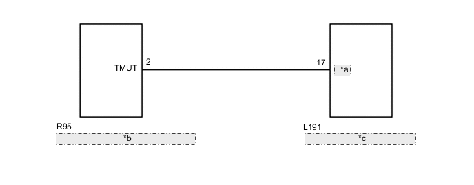
| *a | MUTE |
| *b | Stereo Component Amplifier Assembly |
| *c | DCM (Telematics Transceiver) |
PROCEDURE
-
CHECK DCM (TELEMATICS TRANSCEIVER)
-
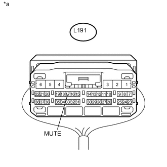
Text in Illustration *a Component with harness connected
(DCM [Telematics Transceiver])
Remove the DCM (telematics transceiver) with its connectors still connected Click here.
-
Measure the voltage according to the value(s) in the table below.
Standard Voltage Tester Connection Condition Specified Condition L191-17 (MUTE) - Body ground Power switch on (ACC), audio system is playing
→ Emergency call mode
Above 3.5 V
→ Below 1 V
OK 
PROCEED TO NEXT SUSPECTED AREA SHOWN IN PROBLEM SYMPTOMS TABLE Click here
NG 
-
-
CHECK HARNESS AND CONNECTOR (STEREO COMPONENT AMPLIFIER ASSEMBLY - DCM [TELEMATICS TRANSCEIVER])
-
Disconnect the R95 stereo component amplifier assembly connector.
-
Disconnect the L191 DCM (telematics transceiver) connector.
-
Measure the resistance according to the value(s) in the table below.
Standard Resistance Tester Connection Condition Specified Condition R95-2 (TMUT) - L191-17 (MUTE) Always Below 1 Ω R95-2 (TMUT) or L191-17 (MUTE) - Body ground Always 10 kΩ or higher
NG
REPAIR OR REPLACE HARNESS OR CONNECTOR
OK
-
-
CHECK STEREO COMPONENT AMPLIFIER ASSEMBLY
-
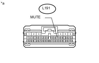
Text in Illustration *a Front view of wire harness connector
(to DCM [Telematics Transceiver])
Reconnect the stereo component amplifier assembly connector.
-
Measure the voltage according to the value(s) in the table below.
Standard Voltage Tester Connection Switch Condition Specified Condition L191-17 (MUTE) - Body ground Power switch on (ACC) Above 3.5 V
OK
REPLACE DCM (TELEMATICS TRANSCEIVER) Click here
NG
REPLACE STEREO COMPONENT AMPLIFIER ASSEMBLY Click here
-