AUDIO AND VISUAL SYSTEM, Diagnostic DTC:B15D3
| DTC Code | DTC Name |
|---|---|
| B15D3 | Stereo Component Amplifier Disconnected |
DESCRIPTION
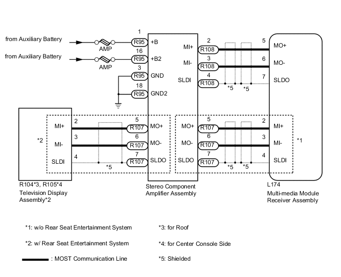
The multi-media module receiver assembly and stereo component amplifier assembly are connected by the MOST communication line.
When a MOST communication error occurs between the multi-media module receiver assembly and stereo component amplifier assembly, this DTC is will be stored.
| DTC Code | DTC Detection Condition | Trouble Area |
|---|---|---|
| B15D3 | A device that is listed in the MOST network connected device record of the master unit is missing. |
|
-
*: w/ Rear Seat Entertainment System
Tech Tips
For the MOST network, the multi-media module receiver assembly is the master unit.
WIRING DIAGRAM
CAUTION / NOTICE / HINT
Note
Inspect the fuses for circuits related to this system before performing the following inspection procedure.
PROCEDURE
-
CHECK OPTIONAL COMPONENTS (INCLUDING ASSOCIATED WIRING)
-
Check that optional components (including associated wiring) which generate radio waves are not installed.
Result Result Proceed to Optional components (including associated wiring) are installed. A Optional components (including associated wiring) are not installed. B Tech Tips
-
Electrical noise from radio waves generated by optional components or the wiring for those components may affect MOST communication.
-
This DTC may be stored when a MOST communication error occurs due to electrical noise.
-
B 
CLEAR DTC Click here
A 
-
-
REMOVE OPTIONAL COMPONENTS (INCLUDING ASSOCIATED WIRING)
-
Remove optional components (including associated wiring).
Note
Do not remove optional components or associated wiring without the permission of the customer.
NEXT
-
-
CLEAR DTC
-
Clear the DTCs Click here.
NEXT
-
-
CHECK FOR DTC
-
Recheck for DTCs and check if the same DTC is output again Click here.
OK No DTCs are output.
OK 
END (COMMUNICATION MALFUNCTION DUE TO NOISE)
NG
-
-
CHECK HARNESS AND CONNECTOR (STEREO COMPONENT AMPLIFIER ASSEMBLY - AUXILIARY BATTERY AND BODY GROUND)
-
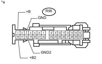
Text in Illustration *a Front view of wire harness connector
(to Stereo Component Amplifier Assembly)
Disconnect the stereo component amplifier assembly connector.
-
Measure the resistance according to the value(s) in the table below.
Standard Resistance Tester Connection Condition Specified Condition R95-3 (GND) - Body ground Always Below 1 Ω R95-18 (GND2) - Body ground Always Below 1 Ω -
Measure the voltage according to the value(s) in the table below.
Standard Voltage Tester Connection Switch Condition Specified Condition R95-1 (+B) - R95-3 (GND) Power switch off 11 to 14 V R95-16 (+B2) - R95-3 (GND) Power switch off 11 to 14 V Result Result Proceed to OK (w/o Rear Seat Entertainment System) A OK (w/ Rear Seat Entertainment System) B NG C
B
CHECK HARNESS AND CONNECTOR (STEREO COMPONENT AMPLIFIER ASSEMBLY - MULTI-MEDIA MODULE RECEIVER ASSEMBLY AND TELEVISION DISPLAY ASSEMBLY) Click here
C
REPAIR OR REPLACE HARNESS OR CONNECTOR
A
-
-
CHECK HARNESS AND CONNECTOR (MULTI-MEDIA MODULE RECEIVER ASSEMBLY - STEREO COMPONENT AMPLIFIER ASSEMBLY)
-
Disconnect the L174 multi-media module receiver assembly connector.
-
Disconnect the R108 stereo component amplifier assembly connector.
-
Measure the resistance according to the value(s) in the table below.
Standard Resistance Tester Connection Condition Specified Condition L174-2 (MI+) - R108-5 (MO+) Always Below 1 Ω L174-3 (MI-) - R108-6 (MO-) Always Below 1 Ω L174-4 (SLDI) - R108-7 (SLDO) Always Below 1 Ω L174-5 (MO+) - R108-2 (MI+) Always Below 1 Ω L174-6 (MO-) - R108-3 (MI-) Always Below 1 Ω L174-7 (SLDO) - R108-4 (SLDI) Always Below 1 Ω L174-2 (MI+) or R108-5 (MO+) - Body ground Always 10 kΩ or higher L174-3 (MI-) or R108-6 (MO-) - Body ground Always 10 kΩ or higher L174-4 (SLDI) or R108-7 (SLDO) - Body ground Always 10 kΩ or higher L174-5 (MO+) or R108-2 (MI+) - Body ground Always 10 kΩ or higher L174-6 (MO-) or R108-3 (MI-) - Body ground Always 10 kΩ or higher L174-7 (SLDO) or R108-4 (SLDI) - Body ground Always 10 kΩ or higher
NG
REPAIR OR REPLACE HARNESS OR CONNECTOR
OK
-
-
CHECK STEREO COMPONENT AMPLIFIER ASSEMBLY
-
Replace the stereo component amplifier assembly with a new or known good one Click here.
NEXT
-
-
CLEAR DTC
-
Clear the DTCs Click here.
NEXT
-
-
CHECK FOR DTC
-
Recheck for DTCs and check if the same DTC is output again Click here.
OK No DTCs are output.
OK
END (STEREO COMPONENT AMPLIFIER ASSEMBLY IS DEFECTIVE)
NG
REPLACE MULTI-MEDIA MODULE RECEIVER ASSEMBLY Click here
-
-
CHECK HARNESS AND CONNECTOR (STEREO COMPONENT AMPLIFIER ASSEMBLY - MULTI-MEDIA MODULE RECEIVER ASSEMBLY AND TELEVISION DISPLAY ASSEMBLY)
-
Disconnect the L174 multi-media module receiver assembly connector.
-
Disconnect the R108 stereo component amplifier assembly connector.
-
Disconnect the R104*1 or R105*2 television display assembly connector.
-
*1: for Roof
-
*2: for Center Console Side
-
-
Measure the resistance according to the value(s) in the table below.
Standard Resistance for Roof Tester Connection Condition Specified Condition L174-5 (MO+) - R108-2 (MI+) Always Below 1 Ω L174-6 (MO-) - R108-3 (MI-) Always Below 1 Ω L174-7 (SLDO) - R108-4 (SLDI) Always Below 1 Ω R108-5 (MO+) - R104-2 (MI+) Always Below 1 Ω R108-6 (MO-) - R104-3 (MI-) Always Below 1 Ω R108-7 (SLDO) - R104-4 (SLDI) Always Below 1 Ω L174-5 (MO+) or R108-2 (MI+) - Body ground Always 10 kΩ or higher L174-6 (MO-) or R108-3 (MI-) - Body ground Always 10 kΩ or higher L174-7 (SLDO) or R108-4 (SLDI) - Body ground Always 10 kΩ or higher R108-5 (MO+) or R104-2 (MI+) - Body ground Always 10 kΩ or higher R108-6 (MO-) or R104-3 (MI-) - Body ground Always 10 kΩ or higher R108-7 (SLDO) or R104-4 (SLDI) - Body ground Always 10 kΩ or higher for Center Console Side Tester Connection Condition Specified Condition L174-5 (MO+) - R108-2 (MI+) Always Below 1 Ω L174-6 (MO-) - R108-3 (MI-) Always Below 1 Ω L174-7 (SLDO) - R108-4 (SLDI) Always Below 1 Ω R108-5 (MO+) - R105-2 (MI+) Always Below 1 Ω R108-6 (MO-) - R105-3 (MI-) Always Below 1 Ω R108-7 (SLDO) - R105-4 (SLDI) Always Below 1 Ω L174-5 (MO+) or R108-2 (MI+) - Body ground Always 10 kΩ or higher L174-6 (MO-) or R108-3 (MI-) - Body ground Always 10 kΩ or higher L174-7 (SLDO) or R108-4 (SLDI) - Body ground Always 10 kΩ or higher R108-5 (MO+) or R105-2 (MI+) - Body ground Always 10 kΩ or higher R108-6 (MO-) or R105-3 (MI-) - Body ground Always 10 kΩ or higher R108-7 (SLDO) or R105-4 (SLDI) - Body ground Always 10 kΩ or higher
NG
REPAIR OR REPLACE HARNESS OR CONNECTOR
OK
-
-
CHECK STEREO COMPONENT AMPLIFIER ASSEMBLY
-
Replace the stereo component amplifier assembly with a new or known good one Click here.
NEXT
-
-
CLEAR DTC
-
Clear the DTCs Click here.
NEXT
-
-
CHECK FOR DTC
-
Recheck for DTCs and check if the same DTC is output again Click here.
OK No DTCs are output.
OK
END (STEREO COMPONENT AMPLIFIER ASSEMBLY IS DEFECTIVE)
NG
REPLACE MULTI-MEDIA MODULE RECEIVER ASSEMBLY Click here
-