AUDIO AND VISUAL SYSTEM, Diagnostic DTC:B15C3
| DTC Code | DTC Name |
|---|---|
| B15C3 | Speaker Output Short |
DESCRIPTION
| DTC Code | DTC Detection Condition | Trouble Area |
|---|---|---|
| B15C3 | A short is detected in the speaker output circuit. |
|
-
*: w/ Telematics Transceiver
WIRING DIAGRAM
CAUTION / NOTICE / HINT
Tech Tips
After the inspection is completed, clear the DTCs.
PROCEDURE
-
CLEAR DTC
-
Clear the DTC Click here.
NEXT 
-
-
CHECK FOR DTC
-
Recheck for DTCs and check if the same DTC is output again Click here.
OK No DTC is output.
OK 
USE SIMULATION METHOD TO CHECK Click here
NG
-
-
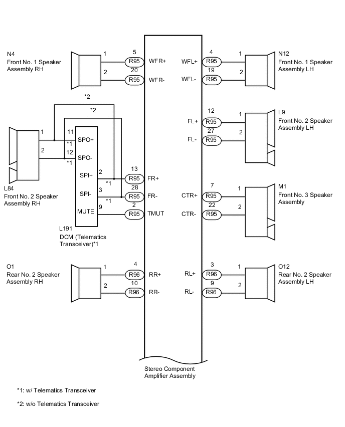
CHECK HARNESS AND CONNECTOR (STEREO COMPONENT AMPLIFIER ASSEMBLY - SPEAKERS AND DCM [TELEMATICS TRANSCEIVER])
-
*1: for RH Side
-
*2: for LH Side
-
*3: w/ Telematics Transceiver
-
*4: w/o Telematics Transceiver
-
Disconnect the R96 and R95 stereo component amplifier assembly connectors.
-
Disconnect the N4*1 and/or N12*2 front No. 1 speaker assembly connector.
-
Disconnect the L84*1 and/or L9*2 front No. 2 speaker assembly connector.
-
Disconnect the M1 front No. 3 speaker assembly connector.
-
Disconnect the O1*1 and/or O12*2 rear No. 2 speaker assembly connector.
-
Disconnect the Q3*1 and/or Q8*2 rear No. 3 speaker assembly connector.
-
Disconnect the R20 floor stereo component speaker assembly connector.
-
Disconnect the R18*1 and/or S18*2 rear header speaker assembly connector.
-
Disconnect the L191 DCM (telematics transceiver) connector.*3
-
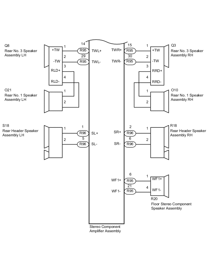
Measure the resistance according to the value(s) in the table below.
Standard Resistance Tester Connection Condition Specified Condition R95-2 (TMUT) - L191-17 (MUTE)*3 Always Below 1 Ω R95-5 (WFR+) - N4-1 Always Below 1 Ω R95-20 (WFR-) - N4-2 Always Below 1 Ω R95-4 (WFL+) - N12-1 Always Below 1 Ω R95-19 (WFL-) - N12-2 Always Below 1 Ω R95-13 (FR+) - L191-2 (SPI+)*3 Always Below 1 Ω R95-28 (FR-) - L191-3 (SPI-)*3 Always Below 1 Ω R95-13 (FR+) - L84-1*4 Always Below 1 Ω R95-28 (FR-) - L84-2*4 Always Below 1 Ω R95-12 (FL+) - L9-1 Always Below 1 Ω R95-27 (FL-) - L9-2 Always Below 1 Ω R95-7 (CTR+) - M1-1 Always Below 1 Ω R95-22 (CTR-) - M1-2 Always Below 1 Ω R96-4 (RR+) - O1-1 Always Below 1 Ω R96-10 (RR-) - O1-2 Always Below 1 Ω R96-3 (RL+) - O12-1 Always Below 1 Ω R96-9 (RL-) - O12-2 Always Below 1 Ω R95-15 (TWR+) - Q3-1 (+TW) Always Below 1 Ω R95-30 (TWR-) - Q3-2 (-TW) Always Below 1 Ω R95-14 (TWL+) - Q8-1 (+TW) Always Below 1 Ω R95-29 (TWL-) - Q8-2 (-TW) Always Below 1 Ω R95-6 (WF1+) - R20-1 (WF1+) Always Below 1 Ω R95-21 (WF1-) - R20-4 (WF1-) Always Below 1 Ω R96-2 (SR+) - R18-1 Always Below 1 Ω R96-6 (SR-) - R18-2 Always Below 1 Ω R96-1 (SL+) - S18-1 Always Below 1 Ω R96-5 (SL-) - S18-2 Always Below 1 Ω R95-2 (TMUT) or L191-17 (MUTE) - Body ground*3 Always 10 kΩ or higher R95-5 (WFR+) or N4-1 - Body ground Always 10 kΩ or higher R95-20 (WFR-) or N4-2 - Body ground Always 10 kΩ or higher R95-4 (WFL+) or N12-1 - Body ground Always 10 kΩ or higher R95-19 (WFL-) or N12-2 - Body ground Always 10 kΩ or higher R95-13 (FR+) or L191-2 (SPI+) - Body ground*3 Always 10 kΩ or higher R95-28 (FR-) or L191-3 (SPI-) - Body ground*3 Always 10 kΩ or higher R95-13 (FR+) or L84-1 - Body ground*4 Always 10 kΩ or higher R95-28 (FR-) or L84-2 - Body ground*4 Always 10 kΩ or higher R95-12 (FL+) or L9-1 - Body ground Always 10 kΩ or higher R95-27 (FL-) or L9-2 - Body ground Always 10 kΩ or higher R95-7 (CTR+) or M1-1 - Body ground Always 10 kΩ or higher R95-22 (CTR-) or M1-2 - Body ground Always 10 kΩ or higher R96-4 (RR+) or O1-1 - Body ground Always 10 kΩ or higher R96-10 (RR-) or O1-2 - Body ground Always 10 kΩ or higher R96-3 (RL+) or O12-1- Body ground Always 10 kΩ or higher R96-9 (RL-) or O12-2 - Body ground Always 10 kΩ or higher R95-15 (TWR+) or Q3-1 (+TW) - Body ground Always 10 kΩ or higher R95-30 (TWR-) or Q3-2 (-TW) - Body ground Always 10 kΩ or higher R95-14 (TWL+) or Q8-1 (+TW) - Body ground Always 10 kΩ or higher R95-29 (TWL-) or Q8-2 (-TW) - Body ground Always 10 kΩ or higher R95-6 (WF1+) or R20-1 (WF1+) - Body ground Always 10 kΩ or higher R95-21 (WF1-) or R20-4 (WF1-) - Body ground Always 10 kΩ or higher R96-2 (SR+) or R18-1 - Body ground Always 10 kΩ or higher R96-6 (SR-) or R18-2 - Body ground Always 10 kΩ or higher R96-1 (SL+) or S18-1 - Body ground Always 10 kΩ or higher R96-5 (SL-) or S18-2 - Body ground Always 10 kΩ or higher Result Result Proceed to OK (w/ Telematics Transceiver) A OK (w/o Telematics Transceiver) B NG C
B 
INSPECT FRONT NO. 2 SPEAKER ASSEMBLY Click here
C
REPAIR OR REPLACE HARNESS OR CONNECTOR
A
-
-
CHECK HARNESS AND CONNECTOR (DCM [TELEMATICS TRANSCEIVER] - FRONT NO. 2 SPEAKER RH)
-
Disconnect the L191 DCM (telematics transceiver) connector.
-
Disconnect the L84 front No. 2 speaker assembly RH connector.
-
Measure the resistance according to the value(s) in the table below.
Standard Resistance Tester Connection Condition Specified Condition L191-5 (SPO+) - L84-1 Always Below 1 Ω L191-6 (SPO-) - L84-2 Always Below 1 Ω L191-5 (SPO+) or L84-1 - Body ground Always 10 kΩ or higher L191-6 (SPO-) or L84-2 - Body ground Always 10 kΩ or higher
NG
REPAIR OR REPLACE HARNESS OR CONNECTOR
OK
-
-
INSPECT DCM (TELEMATICS TRANSCEIVER)
-
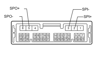
Remove the DCM (telematics transceiver) Click here.
-
Measure the resistance according to the value(s) in the table below.
Standard Resistance Tester Connection Condition Specified Condition 2 (SPI+) - 5 (SPO+) Always Below 1 Ω 3 (SPI-) - 6 (SPO-) Always Below 1 Ω 2 (SPI+) or 5 (SPO+) - Body ground Always 10 kΩ or higher 3 (SPI-) or 6 (SPO-) - Body ground Always 10 kΩ or higher
NG
REPLACE DCM (TELEMATICS TRANSCEIVER) Click here
OK
-
-
INSPECT FRONT NO. 2 SPEAKER ASSEMBLY
-
Remove the front No. 2 speaker assembly Click here.
-
Inspect the front No. 2 speaker assembly Click here.
NG
REPLACE FRONT NO. 2 SPEAKER ASSEMBLY Click here
OK
-
-
INSPECT FRONT NO. 1 SPEAKER ASSEMBLY
-
Remove the front No. 1 speaker assembly Click here.
-
Inspect the front No. 1 speaker assembly Click here.
NG
REPLACE FRONT NO. 1 SPEAKER ASSEMBLY Click here
OK
-
-
INSPECT FRONT NO. 3 SPEAKER ASSEMBLY
-
Remove the front No. 3 speaker assembly Click here.
-
Inspect the front No. 3 speaker assembly Click here.
NG
REPLACE FRONT NO. 3 SPEAKER ASSEMBLY Click here
OK
-
-
INSPECT FLOOR STEREO COMPONENT SPEAKER ASSEMBLY
-
Remove the floor stereo component speaker assembly Click here.
-
Inspect the floor stereo component speaker assembly Click here.
NG
REPLACE FLOOR STEREO COMPONENT SPEAKER ASSEMBLY Click here
OK
-
-
INSPECT REAR NO. 2 SPEAKER ASSEMBLY
-
Remove the rear No. 2 speaker assembly.
-
for Standard Body: Click here.
-
for Long Body: Click here.
-
-
Inspect the rear No. 2 speaker assembly.
-
for Standard Body: Click here.
-
for Long Body: Click here.
Result Result Proceed to OK A NG (for Standard Body) B NG (for Long Body) C -
B
REPLACE REAR NO. 2 SPEAKER ASSEMBLY Click here
C
REPLACE REAR NO. 2 SPEAKER ASSEMBLY Click here
A
-
-
INSPECT REAR NO. 1 SPEAKER ASSEMBLY
-
Remove the rear No. 1 speaker assembly.
-
for Standard Body: Click here.
-
for Long Body: Click here.
-
-
Inspect the rear No. 1 speaker assembly.
-
for Standard Body: Click here.
-
for Long Body: Click here.
Result Result Proceed to OK A NG (for Standard Body) B NG (for Long Body) C -
B
REPLACE REAR NO. 1 SPEAKER ASSEMBLY Click here
C
REPLACE REAR NO. 1 SPEAKER ASSEMBLY Click here
A
-
-
CHECK HARNESS AND CONNECTOR (REAR NO. 3 SPEAKER ASSEMBLY - REAR NO. 1 SPEAKER ASSEMBLY)
-
*1: for LH Side
-
*2: for RH Side
-
Disconnect the Q8*1 or Q3*2 rear No. 3 speaker assembly connector.
-
Disconnect the O21*1 or O10*2 rear No. 1 speaker assembly connector.
-
Measure the resistance according to the value(s) in the table below.
Standard Resistance for LH Side Tester Connection Condition Specified Condition Q8-3 (RLD+) - O21-1 Always Below 1 Ω Q8-4 (RLD-) - O21-2 Always Below 1 Ω Q8-3 (RLD+) or O21-1 - Body ground Always 10 kΩ or higher Q8-4 (RLD-) or O21-2 - Body ground Always 10 kΩ or higher for RH Side Tester Connection Condition Specified Condition Q3-3 (RRD+) - O10-1 Always Below 1 Ω Q3-4 (RRD-) - O10-2 Always Below 1 Ω Q3-3 (RRD+) or O10-1 - Body ground Always 10 kΩ or higher Q3-4 (RRD-) or O10-2 - Body ground Always 10 kΩ or higher
NG
REPLACE DCM (TELEMATICS TRANSCEIVER) Click here
OK
-
-
CHECK REAR NO. 3 SPEAKER ASSEMBLY
-
Replace the rear No. 3 speaker assembly LH and/or RH with a new or known good one.
-
for Standard Body: Click here.
-
for Long Body: Click here.
-
NEXT
-
-
CLEAR DTC
-
Clear the DTCs Click here.
NEXT
-
-
CHECK FOR DTC
-
Recheck for DTCs and check if the same DTC is output again Click here.
OK No DTCs are output.
OK
END (REAR NO. 3 SPEAKER ASSEMBLY IS DEFECTIVE)
NG
-
-
INSPECT REAR HEADER SPEAKER ASSEMBLY
-
Remove the rear header speaker assembly Click here.
-
Inspect the rear header speaker assembly Click here.
OK
REPLACE STEREO COMPONENT AMPLIFIER ASSEMBLY Click here
NG
REPLACE REAR HEADER SPEAKER ASSEMBLY Click here
-