VARIABLE GEAR RATIO STEERING SYSTEM, Diagnostic DTC:C15C1/74, C15C2/74

| DTC Code | DTC Name |
|---|---|
| C15C1/74 | Steering Angle Sensor Malfunction |
| C15C2/74 | Steering Angle Sensor B+ Malfunction |
DESCRIPTION
The steering control ECU detects a steering angle sensor malfunction by receiving an error signal from the steering angle sensor via CAN communication. If the steering control ECU detects this error signal, it will turn the master warning light on, store these DTCs, and stop VGRS operation.
| DTC Code | Detection Condition | Trouble Area |
|---|---|---|
| C15C1/74 | The steering control ECU receives a steering angle sensor malfunction signal via CAN communication |
|
| C15C2/74 | The steering control ECU receives a B+ open circuit signal from the steering angle sensor via CAN communication |
|
WIRING DIAGRAM
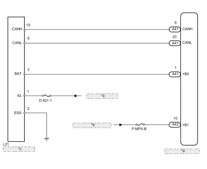
| *a | from D-IG1-1 Relay |
| *b | from Auxiliary Battery |
| *c | Steering Angle Sensor |
| *d | Steering Control ECU |
PROCEDURE
-
CHECK DTC (CAN COMMUNICATION SYSTEM)
-
Check for DTCs in the CAN communication system Click here.
Result Result Proceed to DTC is not output A for LHD:
DTC is output
B for RHD:
DTC is output
C
B 
GO TO CAN COMMUNICATION SYSTEM (HOW TO PROCEED WITH TROUBLESHOOTING) Click here
C
GO TO CAN COMMUNICATION SYSTEM (HOW TO PROCEED WITH TROUBLESHOOTING) Click here
A 
-
-
CHECK HARNESS AND CONNECTOR (STEERING CONTROL ECU +B1 TERMINAL VOLTAGE)
-
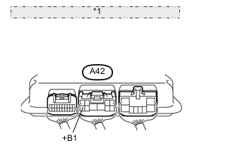
*1 Component with harness connected: (Steering Control ECU) Measure the voltage according to the value(s) in the table below.
Standard voltage Tester Connection Condition Specified Condition A42-10 (+B1) - Body ground Always 11 to 14 V
NG
REPAIR OR REPLACE HARNESS OR CONNECTOR
OK
-
-
CHECK STEERING CONTROL ECU (+B0 TERMINAL VOLTAGE)
-
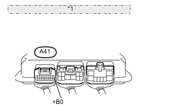
*1 Component with harness connected: (Steering Control ECU) Measure the voltage according to the value(s) in the table below.
Standard voltage Tester Connection Condition Specified Condition A41-1 (+B0) - Body ground Always 11 to 14 V
NG
REPLACE STEERING CONTROL ECU Click here
OK
-
-
CHECK HARNESS AND CONNECTOR (STEERING ANGLE SENSOR)
-
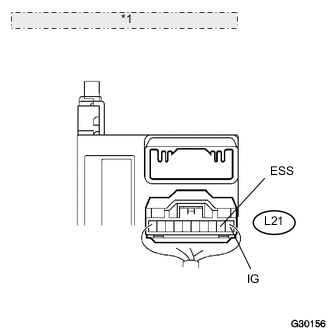
*1 Rear view of wire harness connector: (to Steering Angle Sensor) Disconnect the L21 steering angle sensor connector.
-
Measure the voltage according to the value(s) in the table below.
Standard voltage Tester Connection Condition Specified Condition L21-1 (IG) - Body ground Power switch ON (IG) 11 to 14 V -
Measure the resistance according to the value(s) in the table below.
Standard resistance Tester Connection Condition Specified Condition L21-2 (ESS) - Body ground Always Below 1 Ω
NG
REPAIR OR REPLACE HARNESS OR CONNECTOR
OK
-
-
CHECK STEERING ANGLE SENSOR
-
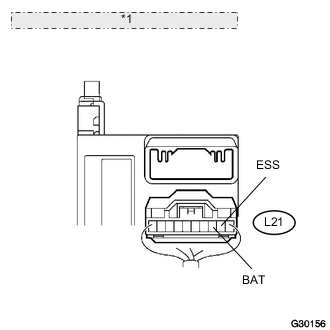
*1 Rear view of wire harness connector: (to Steering Angle Sensor) Disconnect the L21 steering angle sensor connector.
-
Measure the voltage according to the value(s) in the table below.
Standard voltage Tester Connection Condition Specified Condition L21-3 (BAT) - L21-2 (ESS) Power switch ON (IG) 11 to 14 V
OK
REPLACE STEERING ANGLE SENSOR Click here
NG
REPAIR OR REPLACE HARNESS OR CONNECTOR
-