STEERING LOCK SYSTEM Unlock Position Sensor Signal Circuit
DESCRIPTION
The steering lock ECU sends an unlock position signal to the main body ECU. On receiving the signal, the main body ECU permits the hybrid control system start. This prevents the hybrid control system from being started with the steering locked.
The diagnosis information of the steering lock ECU is transmitted to the tester via the certification ECU as the steering lock ECU is not connected to the CAN communication system.
WIRING DIAGRAM
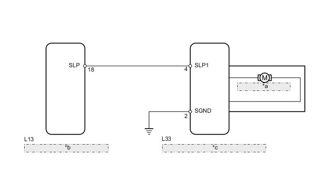
| *a | Steering Lock Motor |
| *b | Main Body ECU (Driver Side Junction Block Assembly) |
| *c | Steering Lock Actuator Assembly (Steering Lock ECU) |
CAUTION / NOTICE / HINT
Tech Tips
When the power switch is OFF, the main body ECU may occasionally go into a non-active state called sleep mode. Therefore, before proceeding with the inspection, it is necessary to perform the following steps to wake up the ECU:
With the power switch OFF, open the driver door. Then (with the power switch still OFF) open and close any door several times at 1.5 second intervals.
PROCEDURE
-
INSPECT STEERING LOCK ECU
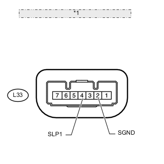
*1 Component with harness connected: (Steering Lock ECU)
-
Measure the voltage according to the value(s) in the table below.
Standard voltage Tester Connection Condition (Steering Lock Position) Specified Condition L33-4 (SLP1) - L33-2 (SGND) Locked 11 to 14 V L33-4 (SLP1) - L33-2 (SGND) Unlocked Below 1 V
OK 
GO TO ENTRY AND START SYSTEM (HOW TO PROCEED WITH TROUBLESHOOTING) Click here
NG 
-
-
CHECK HARNESS AND CONNECTOR (STEERING LOCK ECU - MAIN BODY ECU)
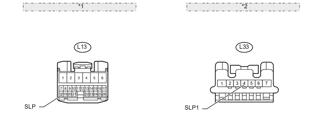
*1 Front view of wire harness connector: (to Main Body ECU) *2 Front view of wire harness connector: (to Steering Lock ECU)
-
Disconnect the L33 steering lock ECU connector.
-
Disconnect the L13 main body ECU connector.
-
Measure the resistance according to the value(s) in the table below.
Standard resistance Tester Connection Condition Specified Condition L33-4 (SLP1) - L13-18 (SLP) Always Below 1 Ω L33-4 (SLP1) or L13-18 (SLP) - Body ground Always 10 kΩ or higher
OK
REPLACE STEERING LOCK ACTUATOR (STEERING LOCK ECU) Click here
NG
REPAIR OR REPLACE HARNESS OR CONNECTOR
-