BRAKE ACTUATOR(for LHD) ON-VEHICLE INSPECTION

PROCEDURE
-
CHECK BRAKE ACTUATOR ASSEMBLY OPERATION
-
Move the shift lever to the P position. Apply the parking brake and connect the intelligent tester to the DLC3.
-
Turn the power switch ON (IG).
-
Turn the intelligent tester on.
-
Enter the following menus: Chassis / ABS/VSC/TRC / Active Test / Actuator Air Bleeding Pattern / Data List / Master Cylinder Sensor, Master Cylinder Sensor 2, FR W/C Sensor, FL W/C Sensor, RR W/C Sensor, RL W/C Sensor.
-
Turn on the Actuator Air Bleeding Pattern test, and check the solenoid (SLA##, SLR##, Electronically Controlled Brake System Solenoid (SMC1), Electronically Controlled Brake System Solenoid (SMC2)).
Note
Do not depress the brake pedal.
Tech Tips
-
It takes approximately 70 seconds to complete the check.
-
The sensors will be checked one by one within the 70 second time period.
-
If incorrect, troubleshoot the brake system Click here.
-
Check the FR W/C Sensor output voltage.
Standard voltage Sensor After starting check (V) 10 to 20 sec. after starting check (V) Master Cylinder Sensor 0.3 to 0.7 0.3 to 0.7 Master Cylinder Sensor 2 0.3 to 0.7 0.3 to 0.7 FR W/C Sensor 2.5 to 4.5 0.3 to 0.7 FL W/C Sensor 0.3 to 0.7 0.3 to 0.7 RR W/C Sensor 0.3 to 0.7 0.3 to 0.7 RL W/C Sensor 0.3 to 0.7 0.3 to 0.7 -
Check the FL W/C Sensor output voltage.
Standard voltage Sensor After starting check (V) 10 to 20 sec. after starting check (V) Master Cylinder Sensor 0.3 to 0.7 0.3 to 0.7 Master Cylinder Sensor 2 0.3 to 0.7 0.3 to 0.7 FR W/C Sensor 0.3 to 0.7 0.3 to 0.7 FL W/C Sensor 2.5 to 4.5 0.3 to 0.7 RR W/C Sensor 0.3 to 0.7 0.3 to 0.7 RL W/C Sensor 0.3 to 0.7 0.3 to 0.7 -
Check the RR W/C Sensor output voltage.
Standard voltage Sensor After starting check (V) 10 to 20 sec. after starting check (V) Master Cylinder Sensor 0.3 to 0.7 0.3 to 0.7 Master Cylinder Sensor 2 0.3 to 0.7 0.3 to 0.7 FR W/C Sensor 0.3 to 0.7 0.3 to 0.7 FL W/C Sensor 0.3 to 0.7 0.3 to 0.7 RR W/C Sensor 2.5 to 4.7 0.3 to 0.7 RL W/C Sensor 0.3 to 0.7 0.3 to 0.7 -
Check the RL W/C Sensor output voltage.
Standard voltage Sensor After starting check (V) 10 to 20 sec. after starting check (V) Master Cylinder Sensor 0.3 to 0.7 0.3 to 0.7 Master Cylinder Sensor 2 0.3 to 0.7 0.3 to 0.7 FR W/C Sensor 0.3 to 0.7 0.3 to 0.7 FL W/C Sensor 0.3 to 0.7 0.3 to 0.7 RR W/C Sensor 0.3 to 0.7 0.3 to 0.7 RL W/C Sensor 2.5 to 4.7 0.3 to 0.7
-
-
Check SMC1, SMC2
-
Enter the following menus: Chassis / ABS/VSC/TRC / Electronically Controlled Brake Utility / Electronically Controlled Brake Invalid / enter Electronically Controlled Brake system Invalid to prohibit the brake control.
-
Check that the brake control warning light comes on.
-
Select: Chassis / ABS/VSC/TRC / Data List / Master Cylinder Sensor, Master Cylinder Sensor 2, FR W/C Sensor and FL W/C Sensor.
-
Check the output voltage by depressing the brake pedal.
Standard voltage Difference in output voltage between "Master Cylinder Sensor" and "FR W/C Sensor" is less than 0.4 V. Difference in output voltage between "Master Cylinder Sensor 2" and "FL W/C Sensor" is less than 0.4 V. -
Select: Chassis / ABS/VSC/TRC / Electronically Controlled Brake Utility / Electronically Controlled Brake Invalid to cancel brake control prohibition (ELECTRONICALLY CONTROLLED BRAKE SYSTEM INVALID).
-
-
-
CHECK PRESSURE SENSOR OPERATION
-
Check the battery voltage.
Standard voltage 11 to 14 V (during engine stop) -
Connect the hydro booster pressure gauge and pedal effort gauge.
-
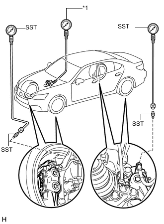
Text in Illustration *1 Pedal Effort Gauge Install the hydro LSPV gauge (SST) and brake pedal effort gauge.
- SST
- 09709-29018
-
Bleed the air from the hydro booster pressure gauge.
-
Move the shift lever to the P position. Connect the intelligent tester to the DLC3 with the parking brake applied.
-
Turn the power switch ON (IG).
-
Clear the DTC Click here.
-
-
Check the wheel cylinder pressure sensor and master pressure sensor.
-
Turn on the intelligent tester. Select: Chassis / ABS/ VSC/TRC / Data List / Master Cylinder Sensor, Master Cylinder Sensor 2, FR W/C Sensor, FL W/C Sensor, RR W/C Sensor, and RL W/C Sensor.
-
Check the brake pedal effort gauge, hydro booster pressure gauge reading, and output pressure voltage. If incorrect, troubleshoot the brake system Click here.
Standard voltage Brake Effort N (kgf, lbf) Master Cylinder Sensor (V) Master Cylinder Sensor 2 (V) 200 (20.4, 45.0) 0.92 to 1.32 0.92 to 1.32 500 (51, 112.4) 2.03 to 2.43 2.03 to 2.43 Standard voltage (18 inch brake caliper (for Type A)) Brake Effort N (kgf, lbf) Front Right Wheel Hydraulic Pressure MPa (kgf/cm2, psi)
FR W/C Sensor (V) 50 (5.1, 11.2) 3.63 to 5.59 (37 to 57, 526 to 810) 1.24 to 1.64 100 (10.2, 22.4) 4.61 to 6.57 (47 to 67, 668 to 952) 1.44 to 1.84 150 (15.3, 34.0) 4.61 to 6.57 (47 to 67, 668 to 952) 1.44 to 1.84 200 (20.4, 45.0) 4.61 to 6.57 (47 to 67, 668 to 952) 1.44 to 1.84 Standard voltage (18 inch brake caliper (for Type B)) Brake Effort N (kgf, lbf) Front Right Wheel Hydraulic Pressure MPa (kgf/cm2, psi)
FR W/C Sensor (V) 50 (5.1, 11.2) 3.23 to 5.19 (33 to 53, 468 to 752) 1.16 to 1.56 100 (10.2, 22.4) 3.87 to 5.83 (39.5 to 59.5, 561 to 845) 1.29 to 1.69 150 (15.3, 34.0) 3.87 to 5.83 (39.5 to 59.5, 561 to 845) 1.29 to 1.69 200 (20.4, 45.0) 4.31 to 6.27 (44 to 64, 625 to 909) 1.38 to 1.78 Standard voltage (19 inch brake caliper) Brake Effort N (kgf, lbf) Front Right Wheel Hydraulic Pressure MPa (kgf/cm2, psi)
FR W/C Sensor (V) 50 (5.1, 11.2) 2.21 to 4.17 (22.5 to 42.5, 320 to 604) 0.95 to 1.35 100 (10.2, 22.4) 3.77 to 5.73 (38.5 to 58.5, 547 to 830) 1.27 to 1.67 150 (15.3, 34.0) 3.77 to 5.73 (38.5 to 58.5, 547 to 830) 1.27 to 1.67 200 (20.4, 45.0) 3.77 to 5.73 (38.5 to 58.5, 547 to 830) 1.27 to 1.67 Standard voltage (18 inch brake caliper (for Type A)) Brake Effort N (kgf, lbf) Front Left Wheel Hydraulic Pressure MPa (kgf/cm2, psi)
FL W/C Sensor (V) 50 (5.1, 11.2) 3.63 to 5.59 (37 to 57, 526 to 810) 1.24 to 1.64 100 (10.2, 22.4) 4.61 to 6.57 (47 to 67, 668 to 952) 1.44 to 1.84 150 (15.3, 34.0) 4.61 to 6.57 (47 to 67, 668 to 952) 1.44 to 1.84 200 (20.4, 45.0) 4.61 to 6.57 (47 to 67, 668 to 952) 1.44 to 1.84 Standard voltage (18 inch brake caliper (for Type B)) Brake Effort N (kgf, lbf) Front Left Wheel Hydraulic Pressure MPa (kgf/cm2, psi)
FL W/C Sensor (V) 50 (5.1, 11.2) 3.23 to 5.19 (33 to 53, 468 to 752) 1.16 to 1.56 100 (10.2, 22.4) 3.87 to 5.83 (39.5 to 59.5, 561 to 845) 1.29 to 1.69 150 (15.3, 34.0) 3.87 to 5.83 (39.5 to 59.5, 561 to 845) 1.29 to 1.69 200 (20.4, 45.0) 4.31 to 6.27 (44 to 64, 625 to 909) 1.38 to 1.78 Standard voltage (19 inch brake caliper) Brake Effort N (kgf, lbf) Front Left Wheel Hydraulic Pressure MPa (kgf/cm2, psi)
FL W/C Sensor (V) 50 (5.1, 11.2) 2.21 to 4.17 (22.5 to 42.5, 320 to 604) 0.95 to 1.35 100 (10.2, 22.4) 3.77 to 5.73 (38.5 to 58.5, 547 to 830) 1.27 to 1.67 150 (15.3, 34.0) 3.77 to 5.73 (38.5 to 58.5, 547 to 830) 1.27 to 1.67 200 (20.4, 45.0) 3.77 to 5.73 (38.5 to 58.5, 547 to 830) 1.27 to 1.67 Standard voltage (18 inch brake caliper (for Type A)) Brake Effort N (kgf, lbf) Rear Right Wheel Hydraulic Pressure MPa (kgf/cm2, psi)
RR W/C Sensor (V) 50 (5.1, 11.2) 3.63 to 5.59 (37 to 57, 526 to 810) 1.24 to 1.64 100 (10.2, 22.4) 4.61 to 6.57 (47 to 67, 668 to 952) 1.44 to 1.84 150 (15.3, 34.0) 4.61 to 6.57 (47 to 67, 668 to 952) 1.44 to 1.84 200 (20.4, 45.0) 4.61 to 6.57 (47 to 67, 668 to 952) 1.44 to 1.84 Standard voltage (18 inch brake caliper (for Type B)) Brake Effort N (kgf, lbf) Rear Right Wheel Hydraulic Pressure MPa (kgf/cm2, psi)
RR W/C Sensor (V) 50 (5.1, 11.2) 3.23 to 5.19 (33 to 53, 468 to 752) 1.16 to 1.56 100 (10.2, 22.4) 3.87 to 5.83 (39.5 to 59.5, 561 to 845) 1.29 to 1.69 150 (15.3, 34.0) 3.87 to 5.83 (39.5 to 59.5, 561 to 845) 1.29 to 1.69 200 (20.4, 45.0) 4.31 to 6.27 (44 to 64, 625 to 909) 1.38 to 1.78 Standard voltage (19 inch brake caliper) Brake Effort N (kgf, lbf) Rear Right Wheel Hydraulic Pressure MPa (kgf/cm2, psi)
RR W/C Sensor (V) 50 (5.1, 11.2) 2.21 to 4.17 (22.5 to 42.5, 320 to 604) 0.95 to 1.35 100 (10.2, 22.4) 3.77 to 5.73 (38.5 to 58.5, 547 to 830) 1.27 to 1.67 150 (15.3, 34.0) 3.77 to 5.73 (38.5 to 58.5, 547 to 830) 1.27 to 1.67 200 (20.4, 45.0) 3.77 to 5.73 (38.5 to 58.5, 547 to 830) 1.27 to 1.67 Standard voltage (18 inch brake caliper (for Type A)) Brake Effort N (kgf, lbf) Rear Left Wheel Hydraulic Pressure MPa (kgf/cm2, psi)
RL W/C Sensor (V) 50 (5.1, 11.2) 3.63 to 5.59 (37 to 57, 526 to 810) 1.24 to 1.64 100 (10.2, 22.4) 4.61 to 6.57 (47 to 67, 668 to 952) 1.44 to 1.84 150 (15.3, 34.0) 4.61 to 6.57 (47 to 67, 668 to 952) 1.44 to 1.84 200 (20.4, 45.0) 4.61 to 6.57 (47 to 67, 668 to 952) 1.44 to 1.84 Standard voltage (18 inch brake caliper (for Type B)) Brake Effort N (kgf, lbf) Rear Left Wheel Hydraulic Pressure MPa (kgf/cm2, psi)
RL W/C Sensor (V) 50 (5.1, 11.2) 3.23 to 5.19 (33 to 53, 468 to 752) 1.16 to 1.56 100 (10.2, 22.4) 3.87 to 5.83 (39.5 to 59.5, 561 to 845) 1.29 to 1.69 150 (15.3, 34.0) 3.87 to 5.83 (39.5 to 59.5, 561 to 845) 1.29 to 1.69 200 (20.4, 45.0) 4.31 to 6.27 (44 to 64, 625 to 909) 1.38 to 1.78 Standard voltage (19 inch brake caliper) Brake Effort N (kgf, lbf) Rear Left Wheel Hydraulic Pressure MPa (kgf/cm2, psi)
RL W/C Sensor (V) 50 (5.1, 11.2) 2.21 to 4.17 (22.5 to 42.5, 320 to 604) 0.95 to 1.35 100 (10.2, 22.4) 3.77 to 5.73 (38.5 to 58.5, 547 to 830) 1.27 to 1.67 150 (15.3, 34.0) 3.77 to 5.73 (38.5 to 58.5, 547 to 830) 1.27 to 1.67 200 (20.4, 45.0) 3.77 to 5.73 (38.5 to 58.5, 547 to 830) 1.27 to 1.67 Tech Tips
For the 18 inch brake caliper (for type A and for type B), refer to the components for the front brake (except 6-pot caliper) Click here.
-
-
Check the accumulator (ACC) pressure sensor.
-
Move the shift lever to the P position. Apply the parking brake and connect the intelligent tester to the DLC3.
-
Turn the power switch ON (IG).
-
Turn on the intelligent tester. Select: Chassis / ABS/ VSC/TRC / Data List / the Accumulator Sensor.
-
Temporarily operate the pump motor by depressing the brake pedal 4 or 5 times.
-
After confirming that the pump motor stops, check the output voltage.
Standard voltage 2.6 to 3.8 V If incorrect, troubleshoot the brake system Click here.
-
-