ELECTRONICALLY CONTROLLED BRAKE SYSTEM, Diagnostic DTC:C1311/11, C1312/12, C1313/13, C1314/14

| DTC Code | DTC Name |
|---|---|
| C1311/11 | Open in Main Relay 1 Circuit |
| C1312/12 | Short in Main Relay 1 Circuit |
| C1313/13 | Open in Main Relay 2 Circuit |
| C1314/14 | Short in Main Relay 2 Circuit |
DESCRIPTION
The ABS main relay (skid control ECU interior circuit) remains ON for approximately 2 minutes after the power switch is turned OFF and the input of brake operation signals stops, and supplies power to the system to keep it ready to operate.
| DTC Code | Information Code | DTC Detection Condition | Trouble Area |
|---|---|---|---|
| C1311/11 | 1 | When either of the following is detected:
|
|
| C1312/12 | 3 | Relay contact is on (BSO1 terminal is 6.5 V or more) for at least 1 second when main relay 1 is off. |
|
| C1313/13 | 4 | When any of the following is detected:
|
|
| C1314/14 | 6 | Relay contact is on (BSO2 terminal is 6.5 V or more) for at least 1 second when main relay 2 is off. |
|
WIRING DIAGRAM
Refer to DTCs C1241/41 and C1242/42 Click here.
CAUTION / NOTICE / HINT
Note
When replacing the skid control ECU, perform the following operations:
-
Initialization of linear solenoid valve and calibration Click here
-
Yaw rate and acceleration sensor zero point calibration Click here
PROCEDURE
-
INSPECT FUSE (ABS MAIN1, ABS MAIN2 AND ABS MAIN3)
-
Remove the ABS MAIN1, ABS MAIN2 and ABS MAIN3 fuses from the engine room No. 2 junction block/relay block.
-
Measure the resistance of the fuses.
Standard resistance Tester Connection Condition Specified Condition ABS MAIN1 fuse Always Below 1 Ω ABS MAIN2 fuse Always Below 1 Ω ABS MAIN3 fuse Always Below 1 Ω
NG 
REPLACE FUSE
OK 
-
-
CHECK TERMINAL VOLTAGE (+BI1, +BI2, +BI3, +BI4)
-
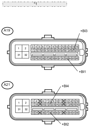
*1 Front view of wire harness connector: (to Skid Control ECU) Disconnect the A19 and A21 ECU connectors.
-
Measure the voltage according to the value(s) in the table below.
Standard voltage Tester Connection Condition Specified Condition A19-43 (+BI1) - Body ground Always 11 to 14 V A21-38 (+BI2) - Body ground Always 11 to 14 V A19-29 (+BI3) - Body ground Always 11 to 14 V A21-22 (+BI4) - Body ground Always 11 to 14 V
NG
REPAIR OR REPLACE HARNESS OR CONNECTOR
OK
-
-
RECONFIRM DTC
-
Clear the DTC Click here.
-
Turn the power switch ON (IG).
-
Check if the same DTCs are recorded Click here.
Tech Tips
Reinstall the sensors, connectors, etc. and restore the vehicle to its prior condition before rechecking for DTCs.
Result Condition Proceed to DTCs (C1311/11, C1312/12, C1313/13 and C1314/14) are not output A DTCs (C1311/11, C1312/12, C1313/13 and C1314/14) are output for LHD B for RHD C
A
USE SIMULATION METHOD TO CHECK Click here
B
REPLACE SKID CONTROL ECU Click here
C
REPLACE SKID CONTROL ECU Click here
-