REAR STABILIZER BAR INSTALLATION
CAUTION / NOTICE / HINT
Tech Tips
A bolt without a torque specification is shown in the standard bolt chart Click here.
PROCEDURE
-
INSTALL REAR STABILIZER BAR
-
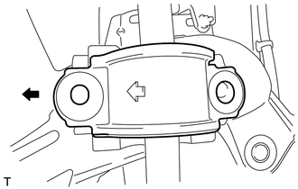
Make sure the bracket's arrows face the front of the vehicle.
Text in Illustration 
Front Side -
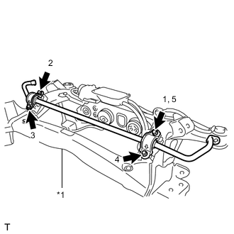
Text in Illustration *1 Rear Suspension Member First, temporarily install bolt 1. Then install bolts 2, 3 and 4. Then tighten bolt 5.
- Torque:
- 51 N*m { 520 kgf*cm, 38 ft.*lbf }
-
-
INSTALL REAR STABILIZER LINK ASSEMBLY LH
-
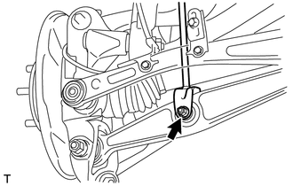
Install the stabilizer link with the nut and bolt.
- Torque:
- 89 N*m { 908 kgf*cm, 69 ft.*lbf }
-
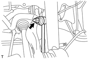
Install the stabilizer link with the nut.
- Torque:
- 26 N*m { 265 kgf*cm, 19 ft.*lbf }
-
-
INSTALL REAR STABILIZER LINK ASSEMBLY RH
Tech Tips
Use the same procedures described for the LH side.
-
INSTALL REAR SUSPENSION MEMBER SUB-ASSEMBLY
-
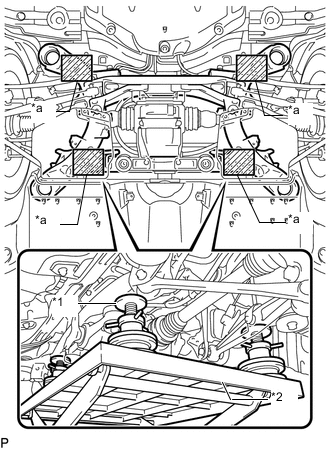
Text in Illustration *1 Attachment *2 Engine Lifter *a Attachment placement location Support the rear suspension member sub-assembly with an engine lifter using 4 attachments or equivalent tools.
Note
-
Make sure to secure the rear suspension member sub-assembly to prevent it from dropping.
-
Use the attachments to keep the rear suspension member sub-assembly level.
-
The rear suspension member sub-assembly is a heavy component. Make sure that it is supported securely.
-
-
Raise the rear suspension member sub-assembly until there is no clearance between the rear suspension member sub-assembly and the body.
Note
When raising the rear suspension member subassembly, be careful not to damage the vehicle body or other components installed on the vehicle.
-
Install the 4 bolts.
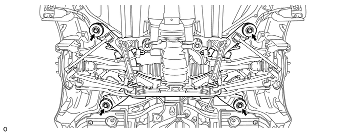
- Torque:
- 127 N*m { 1295 kgf*cm, 94 ft.*lbf }
-
-
TEMPORARILY INSTALL PNEUMATIC CYLINDER WITH REAR SHOCK ABSORBER ASSEMBLY LH
-
TEMPORARILY INSTALL PNEUMATIC CYLINDER WITH REAR SHOCK ABSORBER ASSEMBLY RH
Tech Tips
Use the same procedures described for the LH side.
-
INSTALL REAR DISC BRAKE CALIPER ASSEMBLY LH
-
INSTALL REAR DISC BRAKE CALIPER ASSEMBLY RH
Tech Tips
Use the same procedures described for the LH side.
-
INSTALL LOAD SENSING VALVE SENSOR BRACKET
-
INSTALL REAR HEIGHT CONTROL SENSOR SUB-ASSEMBLY LH
-
INSTALL REAR HEIGHT CONTROL SENSOR SUB-ASSEMBLY RH
Tech Tips
Use the same procedures described for the LH side.
-
INSTALL SKID CONTROL SENSOR WIRE
-
INSTALL REAR WHEEL HOUSE LINER LH
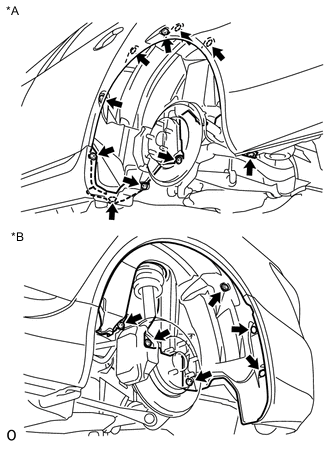
Text in Illustration *1 Front Side *2 Rear Side
-
Install the liner with the 3 screws, 11 nuts, 2 clips to the vehicle side.
-
-
INSTALL PROPELLER SHAFT WITH CENTER BEARING ASSEMBLY
-
INSTALL ELECTRIC PARKING BRAKE ACTUATOR CAP
-
CONNECT WIRE HARNESS CLAMP
-
CONNECT ELECTRIC PARKING BRAKE ACTUATOR CONNECTOR
-
STABILIZE SUSPENSION
-
TIGHTEN PNEUMATIC CYLINDER WITH REAR SHOCK ABSORBER ASSEMBLY LH
-
TIGHTEN PNEUMATIC CYLINDER WITH REAR SHOCK ABSORBER ASSEMBLY RH
Tech Tips
Use the same procedures described for the LH side.
-
INSTALL REAR WHEEL
- Torque:
- 140 N*m { 1428 kgf*cm, 103 ft.*lbf }
-
CHECK SUSPENSION CONTROL SYSTEM
-
Check the suspension control system Click here.
-
-
INSPECT AND ADJUST REAR WHEEL ALIGNMENT
-
Inspect and adjust the rear wheel alignment Click here.
-
-
CHECK SPEED SENSOR SIGNAL
-
Check the speed sensor signal Click here.
-
-
ADJUST HEADLIGHT ASSEMBLY
-
Adjust the headlight Click here.
-
-
ADJUST OBJECT RECOGNITION CAMERA
-
Adjust the object recognition camera Click here.
-