REAR UPPER ARM INSTALLATION

CAUTION / NOTICE / HINT
Tech Tips
-
Use the same procedures for the RH side and LH side.
-
The procedures listed below are for the LH side.
-
A bolt without a torque specification is shown in the standard bolt chart Click here.
PROCEDURE
-
TEMPORARILY CONNECT PNEUMATIC CYLINDER WITH REAR SHOCK ABSORBER ASSEMBLY LH
-
Temporarily connect the pneumatic cylinder lower side with a new nut and washer to the axle carrier.
-
-
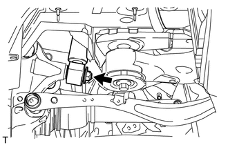
TEMPORARILY INSTALL REAR UPPER NO. 1 CONTROL ARM ASSEMBLY LH
-
Temporarily install the control arm with the bolt, nut and washer to the suspension member.
-
Install the stud of the control arm, and temporarily install a new nut to the axle carrier.
Tech Tips
Push the axle carrier downward.
-
-
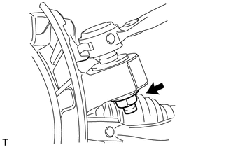
TIGHTEN REAR UPPER NO. 1 CONTROL ARM ASSEMBLY LH
-
Tighten the nut on the control arm.
- Torque:
- 150 N*m { 1530 kgf*cm, 111 ft.*lbf }
-
Tighten the nut on the control arm.
- Torque:
- 160 N*m { 1632 kgf*cm, 118 ft.*lbf }
-
-
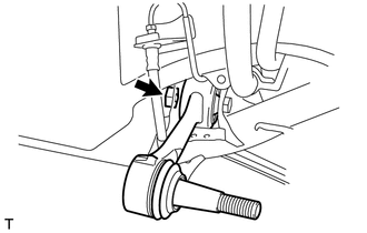
TEMPORARILY INSTALL REAR UPPER NO. 2 CONTROL ARM ASSEMBLY LH
-
Temporarily install the control arm with the bolt, nut and washer to the suspension member.
-
Install the stud of the control arm, and temporarily install a new nut to the axle carrier.
Tech Tips
Push the axle carrier downward.
-
-
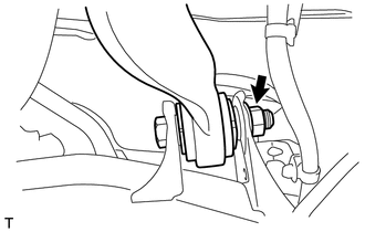
TIGHTEN REAR UPPER NO. 2 CONTROL ARM ASSEMBLY LH
-
Tighten the nut on the rear control arm.
- Torque:
- 225 N*m { 2294 kgf*cm, 166 ft.*lbf }
-
Tighten the nut on the rear control arm.
- Torque:
- 160 N*m { 1632 kgf*cm, 118 ft.*lbf }
-
-
TEMPORARILY INSTALL REAR NO. 2 SUSPENSION ARM ASSEMBLY LH
-
CONNECT TOE CONTROL LINK SUB-ASSEMBLY LH
-
CONNECT REAR NO. 1 SUSPENSION ARM ASSEMBLY LH
-
INSTALL REAR DISC BRAKE CALIPER ASSEMBLY LH
-
STABILIZE SUSPENSION
-
TIGHTEN REAR NO. 2 SUSPENSION ARM ASSEMBLY LH
-
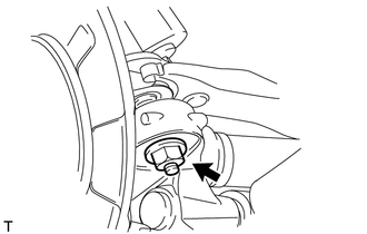
TIGHTEN PNEUMATIC CYLINDER WITH REAR SHOCK ABSORBER ASSEMBLY LH
-
Connect the nut on the axle carrier.
- Torque:
- 80 N*m { 816 kgf*cm, 59 ft.*lbf }
-
-
INSTALL REAR STABILIZER LINK ASSEMBLY LH
-
INSTALL REAR WHEEL
- Torque:
- 140 N*m { 1428 kgf*cm, 103 ft.*lbf }
-
CHECK SUSPENSION CONTROL SYSTEM
-
Check the suspension control system Click here.
-
-
INSPECT AND ADJUST REAR WHEEL ALIGNMENT
-
Inspect and adjust the rear wheel alignment Click here.
-
-
ADJUST HEADLIGHT ASSEMBLY
-
Adjust the headlight Click here.
-
-
ADJUST OBJECT RECOGNITION CAMERA
-
Adjust the object recognition camera Click here.
-