REAR SHOCK ABSORBER REMOVAL

CAUTION / NOTICE / HINT
CAUTION:
Be sure to read the "PRECAUTION" thoroughly before servicing Click here.
Tech Tips
-
Use the same procedures for the RH side and LH side.
-
The procedures listed below are for the LH side.
PROCEDURE
-
REMOVE REAR WHEEL
-
REMOVE REAR SEAT ASSEMBLY
-
for Power Seat:
-
for Ottoman:
-
for Fixed Seat Type:
-
-
REMOVE PACKAGE TRAY TRIM PANEL ASSEMBLY
-
REMOVE NO. 6 ROCKER PANEL MOULDING PROTECTOR
-
REMOVE REAR WHEEL HOUSE LINER LH
-
REMOVE SKID CONTROL SENSOR WIRE
-
REMOVE LOAD SENSING VALVE SENSOR BRACKET
-
DISCONNECT REAR UPPER NO. 2 CONTROL ARM ASSEMBLY LH
-
DISCONNECT REAR UPPER NO. 1 CONTROL ARM ASSEMBLY LH
-
DISCONNECT TOE CONTROL LINK SUB-ASSEMBLY LH
-
REMOVE REAR AXLE SHAFT NUT LH
-
REMOVE REAR SHOCK ABSORBER CAP LH
-
REMOVE ABSORBER CONTROL ACTUATOR
-
REMOVE PNEUMATIC CYLINDER WITH REAR SHOCK ABSORBER ASSEMBLY LH
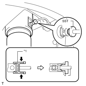
*1 No. 1 Tube Connector *2 Height Control Tube
-
Pinch and pull the tube connector to release it.
-
Using SST, pull out the height control tube from the pneumatic cylinder with rear shock absorber. SST
- SST
- 09730-00010
Note
After pulling out the height control tube, replace the O-ring and plate with new ones.
-
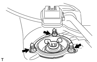
Remove the 3 nuts on the upper side of the shock absorber.
-
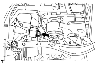
Remove the nut from the lower side of the shock absorber.
-
Angle the axle carrier's upper tip toward the vehicle's outer side, and remove the shock absorber and washer.
-
-
REMOVE HEIGHT CONTROL VALVE O-RING
Tech Tips
It is unnecessary to perform the following procedures if the pneumatic cylinder with shock absorber has been replaced with a new one.
-
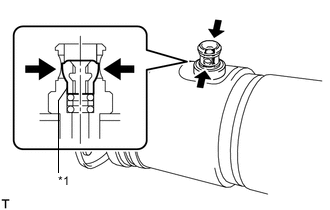
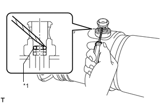
*1 No. 2 Tube Connector Using a screwdriver, detach the 2 clips and remove the tube connector.
-
*1 O-Ring Using a screwdriver, remove the plate and 2 O-rings.
-