ELECTRONICALLY CONTROLLED BRAKE SYSTEM, Diagnostic DTC:C1249/49

| DTC Code | DTC Name |
|---|---|
| C1249/49 | Open in Stop Light Switch Circuit |
DESCRIPTION
The skid control ECU inputs the stop light switch signal and detects braking condition.
The skid control ECU has a circuit for open detection. The skid control ECU outputs the DTC if it detects an open in the stop light signal input line when the stop light switch is off or an open in the stop light circuit (skid control ECU side).
| DTC Code | Information Code | DTC Detection Condition | Trouble Area |
|---|---|---|---|
| C1249/49 | 520 | Stop light switch circuit is open for at least 10 seconds when IG2 terminal voltage is 9.5 V or more. |
|
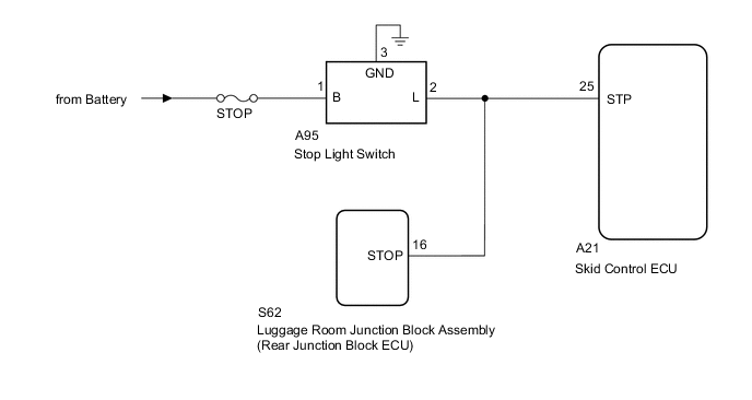
WIRING DIAGRAM
CAUTION / NOTICE / HINT
Note
When replacing the skid control ECU, perform the following operations:
-
Initialization of linear solenoid valve and calibration Click here
-
Yaw rate and acceleration sensor zero point calibration Click here
PROCEDURE
-
INSPECT STOP LIGHT SWITCH
-
Inspect the stop light switch Click here.
OK The stop light switch is normal.
NG 
REPLACE STOP LIGHT SWITCH Click here
OK 
-
-
READ VALUE USING INTELLIGENT TESTER (STOP LIGHT SWITCH)
-
Connect the intelligent tester to the DLC3.
-
Turn the power switch ON (IG).
-
Select the Data List mode on the intelligent tester.
ABS/VSC/TRC: Tester Display Measurement Item/Range Normal Condition Diagnostic Note Stop Light SW Stop light switch / ON or OFF ON: Brake pedal depressed
OFF: Brake pedal released
- -
Check that the stop light observed on the intelligent tester changes when the brake pedal is depressed.
OK When the brake pedal is depressed, the intelligent tester displays "ON". Result Result Proceed to NG (Intelligent tester displays "OFF".) A OK (Intelligent tester displays "ON".) B
B 
CHECK HARNESS AND CONNECTOR (SKID CONTROL ECU - STOP LIGHT SWITCH) Click here
A
-
-
CHECK HARNESS AND CONNECTOR (SKID CONTROL ECU - REAR JUNCTION BLOCKECU)
-
Disconnect the A21 ECU connector.
-
Disconnect the S62 ECU connector.
-
Measure the resistance according to the value(s) in the table below.
Standard resistance Tester Connection Condition Specified Condition A21-25 (STP) - S62-16 (STOP) Always Below 1 Ω
OK
GO TO LIGHTING SYSTEM (HOW TO PROCEED WITH TROUBLESHOOTING) Click here
NG
REPAIR OR REPLACE HARNESS OR CONNECTOR
-
-
CHECK HARNESS AND CONNECTOR (SKID CONTROL ECU - STOP LIGHT SWITCH)
-
Disconnect the A21 ECU connector.
-
Disconnect the A95 switch connector.
-
Measure the resistance according to the value(s) in the table below.
Standard resistance Tester Connection Condition Specified Condition A21-25 (STP) - A95-2 (L) Always Below 1 Ω A21-25 (STP) - Body ground Always 2 kΩ or lower
NG
REPAIR OR REPLACE HARNESS OR CONNECTOR
OK
-
-
RECONFIRM DTC
-
Clear the DTC Click here.
-
Turn the power switch ON (READY).
-
Depress the brake pedal several times to test the stop light circuit.
-
Check if the same DTC is recorded Click here.
Tech Tips
Reinstall the sensors, connectors, etc. and restore the vehicle to its prior condition before rechecking for DTCs.
Result Result Proceed to DTC (C1249/49) is not output A DTC (C1249/49) is output for LHD B for RHD C Tech Tips
If troubleshooting has been carried out according to the "PROBLEM SYMPTOMS TABLE", refer back to the table and proceed to the next step Click here.
A
USE SIMULATION METHOD TO CHECK Click here
B
REPLACE SKID CONTROL ECU Click here
C
REPLACE SKID CONTROL ECU Click here
-