FRONT SUSPENSION MEMBER INSTALLATION

PROCEDURE
-
TEMPORARILY INSTALL FRONT SUSPENSION LOWER ARM ASSEMBLY LH
-
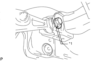
*1 Matchmark Temporarily install the front suspension lower arm LH, and insert the camber adjusting cam from the rear of the vehicle.
-
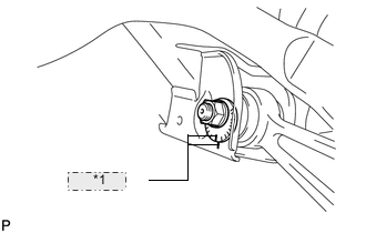
*1 Matchmark Install the No. 2 camber adjusting cam and temporarily install the nut.
Tech Tips
After stabilizing the suspension, tighten the nut.
-
Align the matchmarks of camber adjusting cam, No. 2 camber adjusting cam and front frame assembly.
-
-
TEMPORARILY INSTALL FRONT SUSPENSION LOWER ARM ASSEMBLY RH
Tech Tips
Temporarily install the RH side following the same procedures as the LH side.
-
TEMPORARILY INSTALL FRONT SHOCK ABSORBER LOWER BRACKET SUB-ASSEMBLY LH
-
Connect the front shock absorber lower bracket to the front suspension lower arm LH.
-
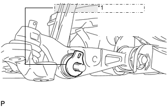
*1 Upper Front Shock Absorber Bracket Plate Align the protrusion of the front shock absorber upper bracket plate with the cutout of the front shock absorber lower bracket, and temporarily install the plate with the nut.
Tech Tips
After stabilizing the suspension, tighten the nut.
-
-
TEMPORARILY INSTALL FRONT SHOCK ABSORBER LOWER BRACKET SUB-ASSEMBLY RH
Tech Tips
Temporarily install the RH side following the same procedures as the LH side.
-
TEMPORARILY INSTALL FRONT NO. 2 SUSPENSION LOWER ARM LH
-
Temporarily install the front No. 2 suspension lower arm LH, and insert the toe adjusting cam from the rear of the vehicle.
-
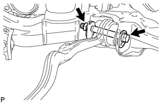
Install the bolt, No. 2 toe adjusting plate and temporarily install the nut.
Tech Tips
After stabilizing the suspension, tighten the nut.
-
Align the matchmarks of camber adjusting cam, No. 2 camber adjusting cam and front frame assembly.
-
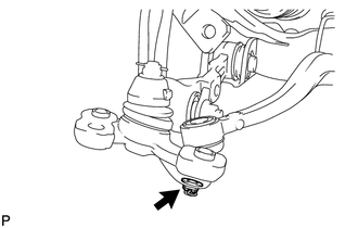
Connect the front suspension lower arm LH to the front lower ball joint with the nut.
- Torque:
- 145 N*m { 1479 kgf*cm, 107 ft.*lbf }
Note
If it is necessary to align the holes for the clips after installing the nuts, the nuts can be tightened up to 60° more.
-
Install a new clip.
-
-
TEMPORARILY INSTALL FRONT NO. 2 SUSPENSION LOWER ARM RH
Tech Tips
Temporarily install the RH side following the same procedures as the LH side.
-
INSTALL POWER STEERING LINK ASSEMBLY
-
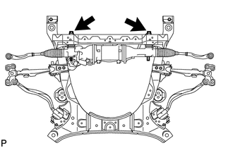
Install the power steering link to the front frame with the 2 bolts, 2 washers and 2 nuts.
- Torque:
- 150 N*m { 1530 kgf*cm, 111 ft.*lbf }
-
-
INSTALL FRONT SUSPENSION MEMBER BRACKET SUB-ASSEMBLY RH
-
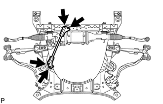
Install the front suspension member bracket with the 4 bolts.
- Torque:
- 59 N*m { 603 kgf*cm, 44 ft.*lbf }
-
-
INSTALL FRONT SUSPENSION MEMBER BRACKET SUB-ASSEMBLY LH
-
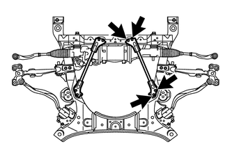
Install the front suspension member bracket with the 4 bolts.
- Torque:
- 59 N*m { 603 kgf*cm, 44 ft.*lbf }
-
-
TEMPORARILY INSTALL FRONT STABILIZER BAR (w/o Active Stabilizer)
-
TEMPORARILY INSTALL FRONT ACTIVE STABILIZER CONTROL ACTUATOR ASSEMBLY (w/ Active Stabilizer)
-
TIGHTEN FRONT NO. 1 STABILIZER BRACKET LH
-
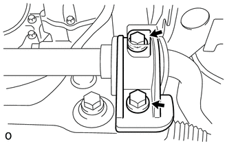
Tighten the front No. 1 stabilizer bracket LH with the 2 bolts.
- Torque:
- 115 N*m { 1173 kgf*cm, 85 ft.*lbf }
-
-
TIGHTEN FRONT NO. 1 STABILIZER BRACKET RH
-
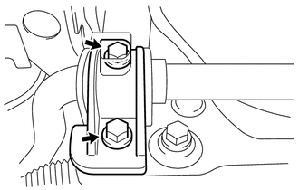
Tighten the front No. 1 stabilizer bracket RH with the 2 bolts.
- Torque:
- 115 N*m { 1173 kgf*cm, 85 ft.*lbf }
-
-
INSTALL FRONT STABILIZER LINK ASSEMBLY LH
-
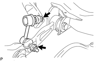
Install the front stabilizer link with the 2 nuts.
- Torque:
- 85 N*m { 867 kgf*cm, 63 ft.*lbf }
Tech Tips
If the ball joint turns together with the nut, use a 6 mm hexagon wrench to hold the stud.
-
-
INSTALL FRONT STABILIZER LINK ASSEMBLY RH
Tech Tips
Install the RH side following the same procedures as the LH side.
-
INSTALL FRONT ENGINE MOUNTING INSULATOR
-
Install the 2 spacers and 2 front engine mounting insulators with the 2 nuts.
- Torque:
- 35 N*m { 357 kgf*cm, 26 ft.*lbf }
-
-
INSTALL FRONT FRAME ASSEMBLY
-
Slowly lower the engine and set it to the front frame assembly.
-
Install the 4 nuts.
- Torque:
- 70 N*m { 714 kgf*cm, 52 ft.*lbf }
-
-
INSTALL ENGINE AND TRANSMISSION ASSEMBLY
-
STABILIZE SUSPENSION
-
TIGHTEN FRONT SUSPENSION LOWER ARM ASSEMBLY LH
-
TIGHTEN FRONT SUSPENSION ARM ASSEMBLY LOWER RH
Tech Tips
Install the RH side following the same procedures as the LH side.
-
TIGHTEN FRONT SHOCK ABSORBER LOWER BRACKET SUB-ASSEMBLY LH
-
TIGHTEN FRONT SHOCK ABSORBER LOWER BRACKET SUB-ASSEMBLY RH
Tech Tips
Install the RH side following the same procedures as the LH side.
-
TIGHTEN FRONT NO. 2 SUSPENSION LOWER ARM LH
-
TIGHTEN FRONT NO. 2 SUSPENSION LOWER ARM RH
Tech Tips
Install the RH side following the same procedures as the LH side.