FRONT SHOCK ABSORBER REMOVAL

CAUTION / NOTICE / HINT
Note
Be sure to read the ''PRECAUTION'' thoroughly before servicing Click here.
Tech Tips
-
Use the same procedures for the RH side and LH side.
-
The procedures listed below are for the LH side.
PROCEDURE
-
REMOVE BATTERY SERVICE HOLE COVER LH
-
PRECAUTION
Note
After turning the power switch off, waiting time may be required before disconnecting the cable from the auxiliary battery terminal. Therefore, make sure to read the disconnecting the cable from the auxiliary battery terminal notice before proceeding with work Click here.
-
DISCONNECT CABLE FROM NEGATIVE AUXILIARY BATTERY TERMINAL
CAUTION:
Wait at least 90 seconds after disconnecting the cable from the negative (-) battery terminal to prevent airbag and seat belt pretensioner activation.
Note
When disconnecting the cable, some systems need to be initialized after the cable is reconnected Click here.
-
REMOVE FRONT WHEEL
-
REMOVE FRONT AXLE SHAFT NUT LH
-
DISCONNECT FRONT DISC BRAKE CALIPER ASSEMBLY LH
-
REMOVE FRONT DISC
-
REMOVE FRONT DISC BRAKE DUST COVER LH
-
DISCONNECT SKID CONTROL SENSOR WIRE
-
REMOVE FRONT SPEED SENSOR LH
-
DISCONNECT TIE ROD ASSEMBLY LH
-
DISCONNECT FRONT NO. 1 SUSPENSION UPPER ARM ASSEMBLY LH
-
DISCONNECT FRONT NO. 2 SUSPENSION UPPER ARM ASSEMBLY LH
-
REMOVE STEERING KNUCKLE SUB-ASSEMBLY LH
-
DISCONNECT FRONT HEIGHT CONTROL SENSOR SUB-ASSEMBLY LH
-
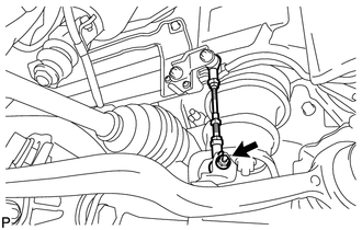
Remove the nut, and then remove the bracket of the front height control sensor LH.
-
-
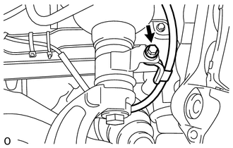
REMOVE FRONT STABILIZER LINK ASSEMBLY LH
-
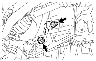
Remove the 2 nuts and front stabilizer link assembly LH.
Tech Tips
If the stud bolt turns with the nut, use a 6 mm hexagon wrench to hold the stud bolt.
-
-
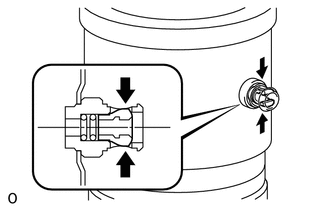
REMOVE AIR CONNECTOR CLIP HOLDER
-
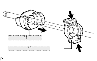
*1 No. 1 Tube Connector *2 Air Connector Clip Holder Pinch and pull the air connector clip holder to release the No. 1 connector.
-
-
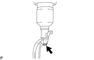
DISCONNECT NO. 4 HEIGHT CONTROL TUBE
-
Pinch and pull the No. 1 tube connector to release it.
-
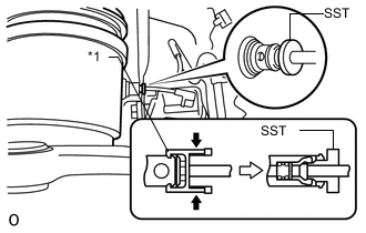
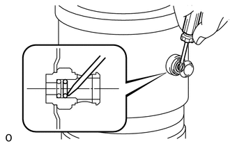
*1 No. 1 Tube Connector Using SST, disconnect the No. 4 height control tube from the pneumatic cylinder with front shock absorber assembly LH.
- SST
- 09730-00010
Note
After pulling out the height control tube, replace the O-ring and plate with new ones.
-
-
REMOVE AIR CLEANER INLET COVER SUB-ASSEMBLY
-
REMOVE ENGINE ROOM SIDE COVER LH
-
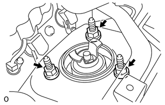
REMOVE FRONT SHOCK ABSORBER CAP LH
-
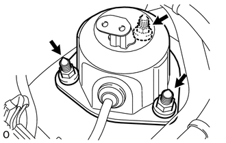
Remove the 3 nuts and front shock absorber cap LH.
-
Disconnect the connector.
-
-
REMOVE ABSORBER CONTROL ACTUATOR
-
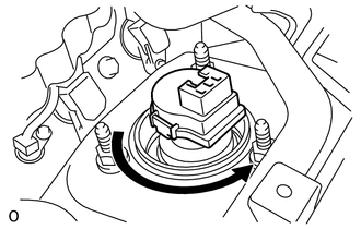
Turn the absorber control actuator counterclockwise 40° and remove it from the pneumatic cylinder with front shock absorber assembly LH.
-
-
REMOVE PNEUMATIC CYLINDER WITH FRONT SHOCK ABSORBER ASSEMBLY LH
-
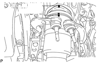
*1 Matchmark When reusing the pneumatic cylinder with front shock absorber assembly LH:
Place matchmarks on the front suspension support assembly and pneumatic cylinder chamber.
-
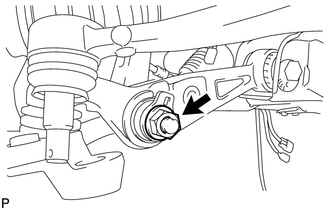
Remove the nut and upper front shock absorber bracket plate, and disconnect the lower front shock absorber bracket sub-assembly LH from the front No. 1 suspension lower arm LH.
-
Remove the bolt, and disconnect the skid control sensor wire from the pneumatic cylinder with front shock absorber assembly LH.
-
Remove the 3 nuts and pneumatic cylinder with front shock absorber assembly LH.
Note
Hold the pneumatic cylinder with front shock absorber assembly LH to prevent it from dropping.
-
-
REMOVE FRONT SHOCK ABSORBER LOWER BRACKET SUB-ASSEMBLY LH
-
Remove the bolt and lower front shock absorber bracket sub-assembly LH.
-
-
REMOVE FRONT PNEUMATIC CYLINDER O-RING LH
Tech Tips
If replacing the pneumatic cylinder with front shock absorber assembly LH with a new one, this procedure is not necessary.
-
Using a screwdriver, detach the 2 clips and remove the tube connector.
-
Using a screwdriver, remove the plate and 2 O-rings.
-