FRONT STABILIZER BAR INSTALLATION
CAUTION / NOTICE / HINT
Tech Tips
A bolt without a torque specification is shown in the standard bolt chart Click here.
PROCEDURE
-
INSTALL FRONT NO. 1 STABILIZER BAR BUSH
-
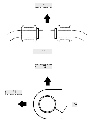
*1 Front Side *2 Bush Stopper *3 Upper Side *4 Seam Install the 2 front No. 1 stabilizer bar bushes outside of the bush stoppers on the front stabilizer bar as shown in the illustration.
Note
Make sure to face the front No. 1 stabilizer bar bush's seam to the lower rear of the vehicle.
-
-
TEMPORARILY INSTALL FRONT STABILIZER BAR
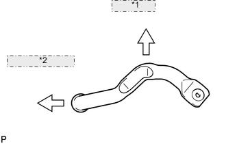
*1 Vehicle Top *2 Vehicle Frontside
-
Temporarily install the front stabilizer bar and front No. 1 stabilizer bracket LH and RH with the 4 bolts in the direction shown in the illustration.
-
-
INSTALL FRONT NO. 1 STABILIZER BRACKET LH
-
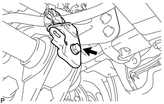
Install the front No. 1 stabilizer bracket LH with the 2 bolts.
- Torque:
- 115 N*m { 1173 kgf*cm, 85 ft.*lbf }
-
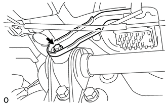
Install the wire harness bracket with the bolt.
- Torque:
- 22 N*m { 224 kgf*cm, 16 ft.*lbf }
-
-
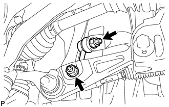
INSTALL FRONT NO. 1 STABILIZER BRACKET RH
-
Install the front No. 1 stabilizer bracket RH with the 2 bolts.
- Torque:
- 115 N*m { 1173 kgf*cm, 85 ft.*lbf }
-
Install the water with motor and bracket pump assembly with the bolt.
- Torque:
- 22 N*m { 224 kgf*cm, 16 ft.*lbf }
-
-
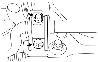
INSTALL FRONT STABILIZER LINK ASSEMBLY LH
-
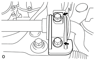
Install the front stabilizer link with the 2 nuts.
- Torque:
- 85 N*m { 867 kgf*cm, 63 ft.*lbf }
Tech Tips
If the ball joint turns together with the nut, use a 6 mm hexagon wrench to hold the stud bolt.
-
-
INSTALL FRONT STABILIZER LINK ASSEMBLY RH
Tech Tips
Install the RH side following the same procedures as the LH side.
-
INSTALL FRONT LOWER SUSPENSION MEMBER PROTECTOR
-
INSTALL NO. 1 ENGINE UNDER COVER
-
INSTALL FRONT WHEEL OPENING EXTENSION PAD LH
-
INSTALL FRONT WHEEL OPENING EXTENSION PAD RH
-
INSTALL NO. 2 ENGINE UNDER COVER
-
INSTALL FRONT CENTER FLOOR COVER