FRONT LOWER SUSPENSION ARM REMOVAL

CAUTION / NOTICE / HINT
Tech Tips
-
Use the same procedures for the RH side and LH side.
-
The procedures listed below are for the LH side.
PROCEDURE
-
REMOVE FRONT WHEEL
-
REMOVE FRONT AXLE SHAFT NUT LH
-
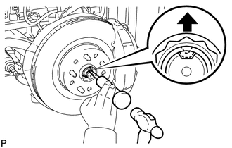
Using SST and a hammer, release the staked part of the front axle shaft nut.
- SST
- 09930-00010
Note
Release the staked part of the nut completely, otherwise the threads of the drive shaft may be damaged.
-
While applying the brakes, remove the front axle shaft nut.
-
-
DISCONNECT FRONT DISC BRAKE CALIPER ASSEMBLY LH
-
REMOVE FRONT DISC
-
REMOVE FRONT DISC BRAKE DUST COVER LH
-
DISCONNECT FRONT HEIGHT CONTROL SENSOR SUB-ASSEMBLY LH
-
REMOVE FRONT NO. 2 SUSPENSION LOWER ARM LH
-
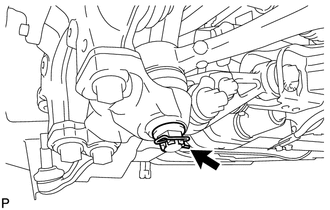
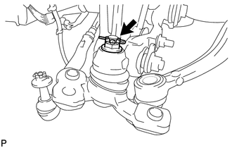
Remove the clip and nut.
-
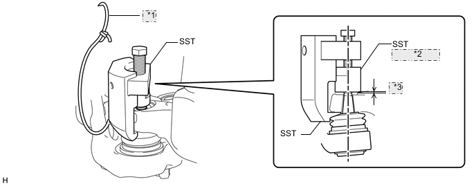
Install SST (attachment) to the front No. 2 suspension lower arm so that there is a space of approximately 2 mm (0.0787 in.) between the front No. 2 suspension lower arm and attachment.
- SST
- 09628-50010 ( 09628-05010 )
Note
As SST may become damaged, make sure the space between the front No. 2 suspension lower arm and attachment is not 2 mm (0.0787 in.) or less.
-
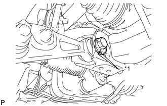
Using SST, remove the front No. 2 suspension lower arm from the lower ball joint assembly.
- SST
- 09628-50010 ( 09628-05010 )
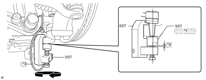
*1 (Attachment) *2 Space of approx 2 mm *3 Tie to Vehicle Note
-
Apply molybdenum grease to the threads and end of the SST bolt.
-
Do not damage the dust cover of the front No. 2 suspension lower arm.
-
Make sure that the bolt of SST and the front No. 2 suspension lower arm are in a straight line when installing SST.
-
Be sure to tie the string of SST to the vehicle to prevent SST from dropping.
-
Do not apply a torque of 160 N*m (1631 kgf*cm, 118 ft.*lbf) or more to SST as it may be damaged.
-
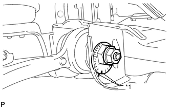
*1 Matchmark Put matchmarks on the front suspension toe adjusting cam and front frame assembly.
-
Put matchmarks on the front suspension No. 2 toe adjusting plate and front frame assembly.
-
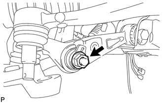
Remove the nut, front suspension No. 2 toe adjusting plate and bolt.
-
Remove the front suspension toe adjusting cam and the front suspension lower arm LH.
-
-
DISCONNECT SKID CONTROL SENSOR WIRE
-
REMOVE FRONT SPEED SENSOR LH
-
DISCONNECT TIE ROD ASSEMBLY LH
-
DISCONNECT FRONT NO. 1 SUSPENSION UPPER ARM ASSEMBLY LH
-
DISCONNECT FRONT NO. 2 SUSPENSION UPPER ARM ASSEMBLY LH
-
REMOVE STEERING KNUCKLE LH
-
REMOVE FRONT LOWER BALL JOINT ASSEMBLY LH
-
Remove the clip and nut.
-
Install SST (attachment) to the front lower ball joint so that there is a space of approximately 2 mm (0.0787 in.) between the front lower ball joint and attachment.
- SST
- 09628-50010 ( 09628-05010 )
Note
-
As SST may become damaged, make sure the front lower ball joint between the arm and attachment is not 2 mm (0.0787 in.) or less.
-
Be sure to install SST (attachment) in order to prevent damage to the lower ball joint stud.
-
Using SST, remove the lower ball joint from the front suspension lower arm.
- SST
- 09628-50010 ( 09628-05010 )
*1 Tie to Vehicle *2 (Attachment) *3 Space of approx 2 mm Note
-
Apply molybdenum grease to the threads and end of the SST bolt.
-
Do not damage the dust cover of the lower arm.
-
Make sure that the bolt of SST and the front No. 2 suspension lower arm are in a straight line when installing SST.
-
Be sure to tie the string of SST to the vehicle to prevent SST from dropping.
-
Do not apply a torque of 160 N*m (1631 kgf*cm, 118 ft.*lbf) or more to SST as it may be damaged.
-
-
REMOVE FRONT STABILIZER LINK ASSEMBLY LH
-
DISCONNECT FRONT SHOCK ABSORBER LOWER BRACKET SUB-ASSEMBLY LH
-
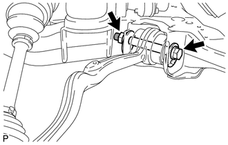
Remove the nut and front shock absorber upper bracket plate, and disconnect the front shock absorber lower bracket from the front suspension lower arm LH.
-
-
REMOVE FRONT SUSPENSION LOWER ARM ASSEMBLY LH
*1 Matchmark
-
Put matchmarks on the camber adjusting cam and front frame assembly.
-
Put matchmarks on the No. 2 camber adjusting cam and front frame assembly.
-
Remove the nut and No. 2 camber adjusting cam.
-
Remove the camber adjusting cam and front suspension lower arm LH.
-