ACTIVE STABILIZER SUSPENSION SYSTEM, Diagnostic DTC:C1915, C1920, C193C
| DTC Code | DTC Name |
|---|---|
| C1915 | Rear PIG Power Supply Voltage |
| C1920 | PIG Wire Harness Malfunction |
| C193C | Front PIG Power Supply Voltage |
DESCRIPTION
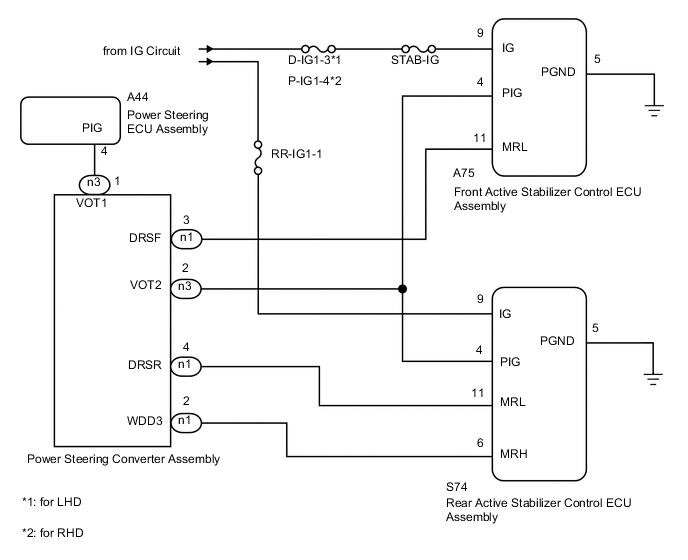
When the PIG power supply (46 V) of the front active stabilizer control ECU and the rear active stabilizer control ECU is not detected, and an irregular voltage is detected, these DTCs are stored. As the power steering converter supplies power to the power steering system in addition to the front and rear active stabilizer control actuators, it is possible for the PIG power supply (46 V) to be cut off as a result of a malfunction in the power steering system. During the initial check that occurs immediately after turning the power switch ON (READY), the condition of the power steering converter is determined. If there is a malfunction, DTC C1915 or C193C is stored.
| DTC Code | Detection Condition | Trouble Area |
|---|---|---|
| C1915 | When one of following conditions is met:
|
|
| C1920 | When one of following conditions is met:
|
|
| C193C | When one of following conditions is met:
|
WIRING DIAGRAM
PROCEDURE
-
CHECK CONNECTOR CONNECTION CONDITION
-
Check that the connectors of the rear active stabilizer control ECU, front active stabilizer control ECU and power steering converter are not loose or disconnected.
OK Connectors are not loose or disconnected
NG 
REPAIR OR REPLACE HARNESS OR CONNECTOR
OK 
-
-
CHECK HARNESS AND CONNECTOR (FRONT AND REAR ACTIVE STABILIZER CONTROL ECU - POWER STEERING CONVERTER AND BODY GROUND)
-
Turn the power switch OFF.
-
Disconnect the S74 rear ECU connector.
-
Disconnect the A75 front ECU connector.
-
Disconnect the n1 and n3 converter connectors.
-
Measure the resistance according to the value(s) in the table below.
Standard resistance Tester Connection Condition Specified Condition S74-4 (PIG) - n3-2 (VOT2) Always Below 1 Ω S74-4 (PIG) - Body ground Always 10 kΩ or higher S74-5 (PGND) - Body ground Always Below 1 Ω S74-6 (MRH) - n1-2 (WDD3) Always Below 1 Ω S74-6 (MRH) - Body ground Always 10 kΩ or higher S74-11 (MRL) - n1-4 (DRSR) Always Below 1 Ω S74-11 (MRL) - Body ground Always 10 kΩ or higher A75-4 (PIG) - n3-2 (VOT2) Always Below 1 Ω A75-4 (PIG) - Body ground Always 10 kΩ or higher A75-5 (PGND) - Body ground Always Below 1 Ω A75-11 (MRL) - n1-3 (DRSF) Always Below 1 Ω A75-11 (MRL) - Body ground Always 10 kΩ or higher
NG
REPAIR OR REPLACE HARNESS OR CONNECTOR
OK
-
-
INSPECT FUSE
-
Turn the power switch OFF.
-
Remove the RR-IG1-1 fuse from the luggage room junction block.
-
Remove the fuse.
-
for LHD:
Remove the D-IG1-3 fuse from the main body ECU (driver side junction block).
-
for RHD:
Remove the P-IG1-4 fuse from the passenger side junction block.
-
-
Remove the STAB-IG fuse from the No. 4 relay block.
-
Measure the resistance according to the value(s) in the table below.
Standard resistance Tester Connection Condition Specified Condition RR-IG1-1 fuse Always Below 1 Ω D-IG1-3 fuse Always Below 1 Ω P-IG1-4 fuse Always Below 1 Ω STAB-IG fuse Always Below 1 Ω
NG
CHECK FOR SHORT IN ALL HARNESSES AND CONNECTORS CONNECTED TO FUSE AND REPLACE FUSE
OK
-
-
CHECK HARNESS AND CONNECTOR (IG VOLTAGE)
-
Turn the power switch OFF.
-
Disconnect the S74 rear ECU connector.
-
Disconnect the A75 front ECU connector.
-
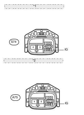
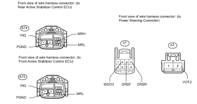
*1 Front view of wire harness connector: (to Rear Active Stabilizer Control ECU) *2 Front view of wire harness connector: (to Front Active Stabilizer Control ECU) Measure the voltage according to the value(s) in the table below.
Standard voltage Tester Connection Switch Condition Specified Condition S74-9 (IG) - Body ground Power switch ON (IG) 11 to 14 V A75-9 (IG) - Body ground Power switch ON (IG) 11 to 14 V
NG
REPAIR OR REPLACE HARNESS OR CONNECTOR
OK
-
-
CHECK DTC (POWER STEERING SYSTEM)
-
Turn the power switch OFF.
-
Connect the intelligent tester to the DLC3.
-
Turn the power switch ON (READY) and the tester ON.
-
Check if power steering system DTC C1568 is output Click here.
Result Result Proceed to DTC is output A DTC is not output B
B 
REPLACE FRONT ACTIVE STABILIZER CONTROL ECU Click here
A
-
-
CHECK HARNESS AND CONNECTOR (POWER STEERING CONVERTER - POWER STEERING ECU)
-
Turn the power switch OFF.
-
Disconnect the n3 converter connector.
-
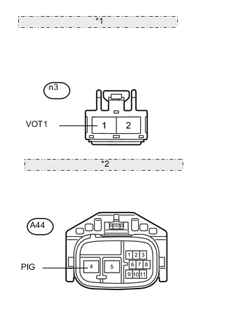
*1 Front view of wire harness connector: (to Power Steering Converter) *2 Front view of wire harness connector: (to Power Steering ECU) Disconnect the A44 power steering ECU connector.
-
Measure the resistance according to the value(s) in the table below.
Standard resistance Tester Connection Condition Specified Condition n3-1 (VOT1) - A44-4 (PIG) Always Below 1 Ω n3-1 (VOT1) - Body ground Always 10 kΩ or higher
NG
REPAIR OR REPLACE HARNESS OR CONNECTOR
OK
-
-
REPLACE FRONT ACTIVE STABILIZER CONTROL ECU
-
Turn the power switch OFF.
-
Replace the front active stabilizer control ECU with a new one Click here.
NEXT
-
-
CLEAR DTC
-
Turn the power switch OFF.
-
Connect the intelligent tester to the DLC3.
-
Clear the DTCs Click here.
NEXT
-
-
CHECK DTC
-
Turn the power switch OFF.
-
Connect the intelligent tester to the DLC3
-
Turn the power switch ON (READY) and wait 30 seconds or more. Then check for DTCs Click here.
Result Result Proceed to DTC output A DTC not output B
B
SECURELY INSTALL FRONT ACTIVE STABILIZER CONTROL ECU Click here
A
-
-
REPLACE REAR ACTIVE STABILIZER CONTROL ECU
-
Turn the power switch OFF.
-
Replace the new front active stabilizer control ECU with the originally installed front active stabilizer control ECU Click here.
-
Replace the rear active stabilizer control ECU with a new one Click here.
Tech Tips
The front active stabilizer control ECU and rear active stabilizer control ECU are identical.
NEXT
-
-
CLEAR DTC
-
Turn the power switch OFF.
-
Connect the intelligent tester to the DLC3.
-
Clear the DTCs Click here.
NEXT
-
-
CHECK DTC
-
Turn the power switch OFF.
-
Connect the intelligent tester to the DLC3.
-
Turn the power switch ON (READY) and wait 30 seconds or more. Then check for DTCs Click here.
Result Result Proceed to DTC output A DTC not output B
A
REPLACE POWER STEERING CONVERTER ASSEMBLY Click here
B
SECURELY INSTALL REAR ACTIVE STABILIZER CONTROL ECU Click here
-