AIR SUSPENSION SYSTEM TS and CG Terminal Circuit
DESCRIPTION
With terminals 12 (TS) and 4 (CG) of the DLC3 connected, when the power switch is turned ON (IG), test mode will start and then the DTCs will be output.
WIRING DIAGRAM
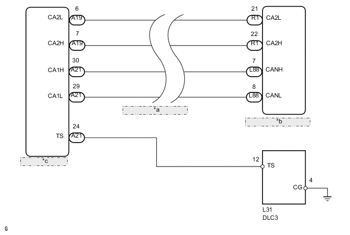
| *a | CAN Communication Line |
| *b | Suspension Control ECU |
| *c | Skid Control ECU |
CAUTION / NOTICE / HINT
Note
When replacing the skid control ECU, perform initialization of the linear solenoid valve calibration Click here.
PROCEDURE
-
INSPECT DLC3 (TS VOLTAGE)
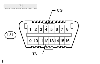
*1 Front view of DLC3:
-
Measure the voltage according to the value(s) in the table below.
Standard voltage Tester Connection Switch Condition Specified Condition L31-12 (TS) - L31-4 (CG) Power switch ON (IG) 11 to 14 V
OK 
PROCEED TO NEXT CIRCUIT INSPECTION SHOWN IN PROBLEM SYMPTOMS TABLE Click here
NG 
-
-
CHECK HARNESS AND CONNECTOR (DLC3 - SKID CONTROL ECU AND BODY GROUND)
-
Disconnect the A21 skid control ECU connector.
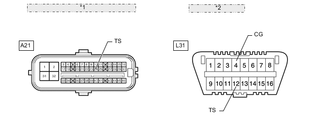
*1 Front view of wire harness connector: (to Skid Control ECU) *2 Front view of DLC3: -
Measure the resistance according to the value(s) in the table below.
Standard resistance Tester Connection Condition Specified Condition L31-12 (TS) - A21-24 (TS) Always Below 1 Ω L31-12 (TS) or A21-24 (TS) - Body ground Always 10 kΩ or higher L31-4 (CG) - Body ground Always Below 1 Ω Result Result Proceed to NG A OK (for LHD) B OK (for RHD) C
A
REPAIR OR REPLACE HARNESS OR CONNECTOR
B
REPLACE SKID CONTROL ECU Click here
C
REPLACE SKID CONTROL ECU Click here
-