REAR AXLE HUB INSTALLATION

CAUTION / NOTICE / HINT
Tech Tips
-
Use the same procedures for the RH side and LH side.
-
The procedures listed below are for the LH side.
-
A bolt without a torque specification is shown in the standard bolt chart ( Click here).
PROCEDURE
-
INSTALL REAR AXLE HUB AND BEARING ASSEMBLY LH
-
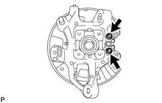
Install the parking brake plate, cable support bracket and parking brake anchor block to the rear axle carrier with the 2 nuts.
- Torque:
- 76 N*m { 775 kgf*cm, 56 ft.*lbf }
-
Hold the axle hub and bearing in a vise between aluminum plates.
Note
Do not overtighten the vise.
-
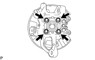
Install the axle hub and bearing to the rear axle carrier with the 4 bolts.
- Torque:
- 97 N*m { 989 kgf*cm, 72 ft.*lbf }
-
-
INSTALL REAR NO. 1 WHEEL BEARING DUST DEFLECTOR LH
-
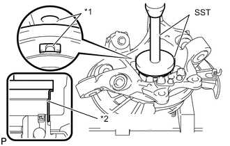
*1 Matchmark *2 Dust Deflector Using SST and a hammer, install the No. 1 bearing dust deflector to the rear axle carrier.
- SST
- 09950-70010 ( 09951-07150 )
- 09951-01000
Tech Tips
Align the hole for the speed sensor in the No. 1 bearing dust deflector with the rear axle carrier.
-
-
INSTALL REAR AXLE ASSEMBLY LH
-
Engage the spline part of the rear axle carrier to the spline part of the driver shaft assembly.
-
Using a jack, lift up the rear axle carrier, and align the installation positions of each arm.
Note
Place a wooden block between the jack and rear axle carrier to prevent damage.
-
-
TEMPORARILY CONNECT PNEUMATIC CYLINDER WITH REAR SHOCK ABSORBER ASSEMBLY LH
-
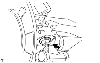
CONNECT REAR UPPER NO. 1 CONTROL ARM ASSEMBLY LH
-
Connect the control arm with a new nut to the axle carrier.
- Torque:
- 160 N*m { 1632 kgf*cm, 118 ft.*lbf }
-
-
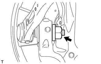
CONNECT REAR UPPER NO. 2 CONTROL ARM ASSEMBLY LH
-
Connect the control arm with a new nut to the axle carrier.
- Torque:
- 160 N*m { 1632 kgf*cm, 118 ft.*lbf }
-
-
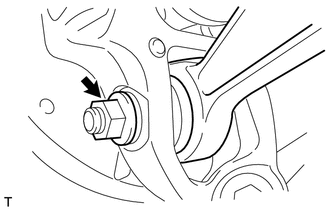
CONNECT TOE CONTROL LINK SUB-ASSEMBLY LH
-
Connect the control link with a new nut to the axle carrier.
- Torque:
- 118 N*m { 1203 kgf*cm, 87 ft.*lbf }
-
-
TEMPORARILY TIGHTEN REAR NO. 2 SUSPENSION ARM ASSEMBLY LH
-
Install the stud of the suspension arm, and temporarily install a washer, nut and the bolt to the axle carrier.
-
*1 No. 2 Suspension Toe Adjust Plate Temporarily install the No. 2 suspension arm with the No. 2 suspension toe adjust plate, rear suspension toe adjust cam and nut to the suspension member.
-
-
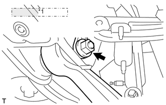
CONNECT REAR NO. 1 SUSPENSION ARM ASSEMBLY LH
-
Connect the suspension arm with a new nut to the axle carrier.
- Torque:
- 118 N*m { 1203 kgf*cm, 87 ft.*lbf }
-
-
INSTALL PARKING BRAKE ASSEMBLY
-
INSTALL REAR AXLE SHAFT NUT LH
-
Clean the threaded parts on the drive shaft and axle hub nut using a non-residue solvent.
Note
-
Be sure to perform this work for a new drive shaft.
-
Keep the threaded parts free of oil and foreign objects.
-
-
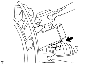
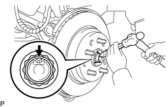
Using a 32 mm socket wrench, install a new rear axle shaft nut.
- Torque:
- 290 N*m { 2957 kgf*cm, 214 ft.*lbf }
Note
Do not stake the shaft nut.
Tech Tips
Stake the shaft nut after the axle hub bearing looseness and axle hub runout inspections.
-
-
INSPECT REAR AXLE HUB BEARING LOOSENESS
-
INSPECT REAR AXLE HUB RUNOUT
-
INSTALL REAR DISC
-
ADJUST PARKING BRAKE SHOE CLEARANCE
-
CONNECT SPEED SENSOR REAR LH
-
CONNECT REAR DISC BRAKE CALIPER ASSEMBLY LH
-
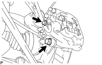
Connect the rear disc brake caliper assembly LH with new 2 bolts.
- Torque:
- 86 N*m { 877 kgf*cm, 63 ft.*lbf }
Note
-
Do not twist the flexible hose.
-
Make sure the screw parts are free from foreign matter and are not damaged.
-
Be careful not to overtighten the bolts, as the rear axle carrier is made of aluminum.
-
-
STAKE REAR AXLE SHAFT LH NUT
-
Using a chisel and a hammer, stake the axle shaft nut.
-
-
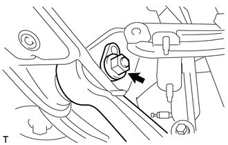
INSTALL LOAD SENSING VALVE SENSOR BRACKET
-
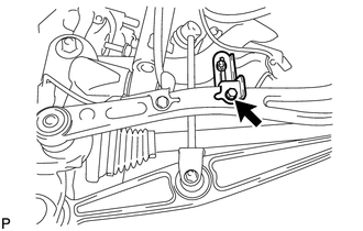
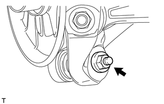
Install the load sensing valve sensor bracket to the toe control link sub-assembly with the bolt.
- Torque:
- 3.6 N*m { 37 kgf*cm, 70 kgf*cm, 32 in.*lbf, 61 in.*lbf }
-
-
STABILIZE SUSPENSION
-
CONNECT PNEUMATIC CYLINDER WITH REAR SHOCK ABSORBER ASSEMBLY LH
-
CONNECT REAR STABILIZER LINK ASSEMBLY LH
-
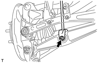
Insert the bolt from the front of the vehicle. Then install the rear stabilizer link assembly LH with the nut.
- Torque:
- 26 N*m { 265 kgf*cm, 19 ft.*lbf }
-
-
TIGHTEN REAR NO. 2 SUSPENSION ARM ASSEMBLY LH
-
Tighten the nut on the rear suspension member side.
- Torque:
- 150 N*m { 1530 kgf*cm, 111 ft.*lbf }
-
Tighten the nut on the rear axle carrier side.
- Torque:
- 225 N*m { 2294 kgf*cm, 166 ft.*lbf }
-
-
INSTALL REAR WHEEL
- Torque:
- 140 N*m { 1428 kgf*cm, 103 ft.*lbf }
-
PERFORM PARKING BRAKE SHOE BEDDING
-
Perform parking brake shoe bedding Click here.
-
-
INSPECT AND ADJUST REAR WHEEL ALIGNMENT
-
Inspect and adjust rear wheel alignment ( Click here).
-
-
CHECK ABS SPEED SENSOR SIGNAL
-
Check the speed sensor signal ( Click here).
-
-
ADJUST HEADLIGHT ASSEMBLY
-
Adjust the headlight Click here.
-
-
ADJUST OBJECT RECOGNITION CAMERA
-
Adjust the object recognition camera Click here.
-