FRONT DRIVE SHAFT ASSEMBLY INSTALLATION

PROCEDURE
-
INSTALL FRONT DRIVE SHAFT HOLE SNAP RING LH
-
Install a new front drive shaft hole snap ring LH.
-
-
INSTALL FRONT DRIVE SHAFT ASSEMBLY LH
-
Coat the spline of the inboard joint shaft assembly with MP grease.
-
Set the front drive shaft hole snap ring LH with the opening side facing down.
-
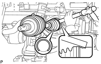
Align the shaft splines and install the drive shaft assembly LH with a brass bar and hammer.
Note
-
Make sure that the snap ring opening is facing downwards when installing the front drive shaft assembly.
-
Be careful not to damage the drive shaft dust cover, boot and oil seal.
-
Move the drive shaft assembly while keeping it level.
-
Bending or sliding the drive shaft excessively may cause the tripod joint to come out of its groove. Therefore, be careful when handling or installing the drive shaft.
Tech Tips
Whether or not the inboard joint shaft is in contact with the pinion shaft can be determined from the sound and feeling when tapping in the shaft.
-
-
-
INSTALL FRONT DRIVE SHAFT ASSEMBLY RH
-
Align the shaft splines and install the drive shaft assembly RH.
Note
-
Be careful not to damage the drive shaft dust cover, boot and oil seal.
-
Move the drive shaft assembly while keeping it level.
-
-
Using water pump pliers, install a new drive shaft bearing bracket hole snap ring.
-
Install a new bolt.
- Torque:
- 32 N*m { 326 kgf*cm, 24 ft.*lbf }
Note
Before installing the bolt, check that there is rubber on the tip of the bolt. If there is no rubber on the bolt, use a new one.
-
Install the wire harness bracket with the bolt.
- Torque:
- 12 N*m { 122 kgf*cm, 9 ft.*lbf }
-
-
INSTALL FRONT AXLE ASSEMBLY LH
-
INSTALL FRONT AXLE ASSEMBLY RH
Tech Tips
Use the same procedure described for the LH side.