TRANSFER ASSEMBLY REMOVAL

PROCEDURE
-
PRECAUTION
Note
After turning the power switch off, waiting time may be required before disconnecting the cable from the auxiliary battery terminal. Therefore, make sure to read the disconnecting the cable from the auxiliary battery terminal notice before proceeding with work Click here.
-
REMOVE FRONT WHEEL
-
REMOVE LUGGAGE COMPARTMENT MAT SUB-ASSEMBLY (w/ Spare Tire)
-
REMOVE DECK BOARD ASSEMBLY (w/o Spare Tire)
-
REMOVE DECK TRIM SIDE BOARD LH (w/o Spare Tire)
-
REMOVE BATTERY SERVICE HOLE COVER LH
-
DISCONNECT CABLE FROM NEGATIVE AUXILIARY BATTERY TERMINAL
Note
When disconnecting the cable, some systems need to be initialized after the cable is reconnected Click here.
-
REMOVE SERVICE PLUG GRIP
-
REMOVE V-BANK COVER SUB-ASSEMBLY
-
REMOVE AIR CLEANER INLET COVER SUB-ASSEMBLY
-
REMOVE NO. 1 AIR CLEANER INLET
-
REMOVE ENGINE ROOM SIDE COVER RH
-
REMOVE ENGINE ROOM SIDE COVER LH
-
REMOVE COWL TOP VENTILATOR LOUVER RH (for LHD)
-
REMOVE COWL TOP VENTILATOR LOUVER LH (for RHD)
-
REMOVE MOTOR CABLE COVER RH (for LHD)
-
REMOVE MOTOR CABLE COVER LH (for RHD)
-
REMOVE INVERTER COVER ASSEMBLY RH (for LHD)
-
REMOVE INVERTER COVER ASSEMBLY LH (for RHD)
-
REMOVE CONNECTOR COVER ASSEMBLY (for LHD)
-
CHECK TERMINAL VOLTAGE (for LHD)
-
INSTALL CONNECTOR COVER ASSEMBLY (for LHD)
-
REMOVE CONNECTOR COVER ASSEMBLY (for RHD)
-
CHECK TERMINAL VOLTAGE (for RHD)
-
INSTALL CONNECTOR COVER ASSEMBLY (for RHD)
-
REMOVE FRONT CENTER FLOOR COVER (w/ Cover)
-
REMOVE NO. 2 ENGINE UNDER COVER
-
REMOVE FRONT WHEEL OPENING EXTENSION PAD RH
-
REMOVE FRONT WHEEL OPENING EXTENSION PAD LH
-
REMOVE NO. 1 ENGINE UNDER COVER
-
REMOVE FRONT LOWER SUSPENSION MEMBER PROTECTOR
-
REMOVE FRONT EXHAUST PIPE ASSEMBLY
-
REMOVE PROPELLER SHAFT WITH CENTER BEARING ASSEMBLY
-
DISCONNECT FLOOR SHIFT GEAR SHIFTING ROD SUB-ASSEMBLY
-
LOOSEN FRONT PROPELLER SHAFT ASSEMBLY
-
DRAIN TRANSFER OIL
-
REMOVE TRANSFER ASSEMBLY
-
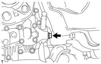
Remove the bolt and disconnect the ground cable.
-
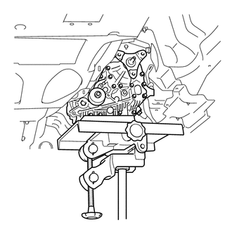
Using a jack and wooden blocks or equivalent, support the transfer.
Note
Do not set the wooden blocks or equivalent against the oil pan of the transmission.
-
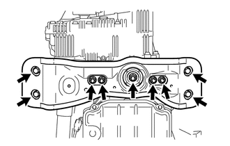
Remove the 4 bolts, 5 nuts, No. 3 rear engine mounting insulator and rear engine mounting member.
-
While supporting the front propeller shaft assembly by hand, remove the 12 bolts and 4 universal joint washers.
-
Remove the front propeller shaft assembly from each companion flange.
Note
Do not bend the front propeller shaft at an excessive angle.
-
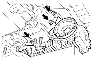
Remove the 3 bolts.
-
Install the rear engine mounting member and No. 3 rear engine mounting insulator with the 4 bolts and 5 nuts.
-
Set an engine lift and wooden blocks or equivalent against the rear engine mounting member and support the hybrid vehicle transmission.
Note
Do not set the wooden blocks or equivalent against the oil pan of the transmission.
-
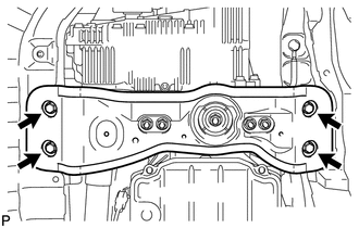
Remove the 4 bolts and disconnect the rear engine mounting member.
-
Slowly tilt the hybrid vehicle transmission away from the vehicle.
Note
Be careful of the exhaust manifold and wire harnesses when tilting the transmission.
-
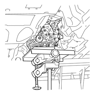
Make sure the wooden blocks or equivalent are set securely against the transfer with the jack.
-
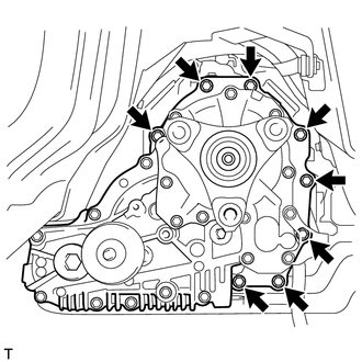
Remove the 8 bolts and transfer.
Note
-
Do not damage the oil seal.
-
Be careful not to drop the transfer assembly.
-
Be sure to perform this procedure with several people as the transfer assembly is very heavy.
-
-
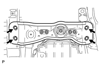
Connect the rear engine mounting member with the 4 bolts.
-