OIL PUMP ASSEMBLY INSTALLATION

PROCEDURE
-
INSTALL OIL WITH MOTOR PUMP ASSEMBLY
-
Install a new gasket to the oil with motor pump assembly.
-
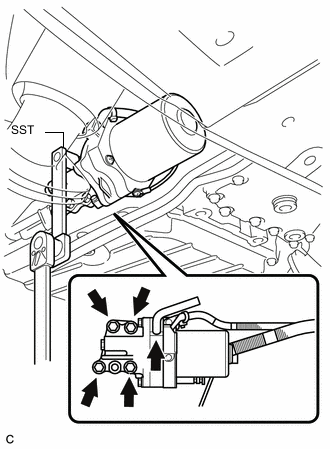
Using SST, install the oil with motor pump assembly with the 4 bolts.
- SST
- 09961-00950
- Torque:
- without SST
- 32 N*m { 321 kgf*cm, 24 ft.*lbf }
- with SST
- 18 N*m { 180 kgf*cm, 13 ft.*lbf }
Tech Tips
-
Use a torque wrench with a fulcrum length of 180 mm (7.09 in.).
-
If using a torque wrench with a length other than 180 mm (7.09 in.), the specified torque value must be recalculated.
-
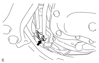
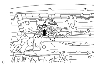
Connect the transmission breather hose.
-
-
INSTALL OIL COOLER TUBE (for LHD)
-
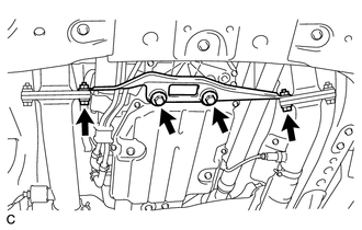
Install the oil cooler tube with the 2 clips and the 3 bolts in the order shown in the illustration.
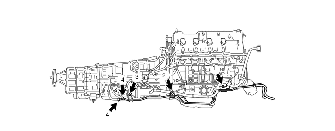
- Torque:
- 12 N*m { 122 kgf*cm, 9 ft.*lbf }
-
-
INSTALL OIL COOLER TUBE (for RHD)
-
Install the oil cooler tube with the 2 clips and the 3 bolts in the order shown in the illustration.
- Torque:
- 12 N*m { 122 kgf*cm, 9 ft.*lbf }
-
Install the wire harness clamp bracket with the bolt.
- Torque:
- 12 N*m { 122 kgf*cm, 9 ft.*lbf }
-
-
CONNECT OUTLET NO. 1 HYBRID WATER PUMP PIPE (for LHD)
-
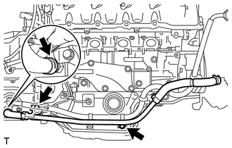
Install the outlet No. 1 hybrid water pump pipe with the 2 bolts.
- Torque:
- 22 N*m { 224 kgf*cm, 16 ft.*lbf }
-
Secure the hose with the clip.
-
Secure the hose with the clip.
-
-
CONNECT WIRE HARNESS
-
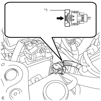
Install the 9 wire harness clamps and connector to the hybrid vehicle transmission assembly.
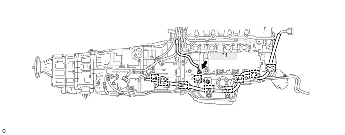
*1 Connector
-
-
INSTALL NO. 1 EXHAUST PIPE SUPPORT BRACKET SUB-ASSEMBLY
-
Install the bracket with the 2 bolts.
- Torque:
- 43 N*m { 438 kgf*cm, 32 ft.*lbf }
-
Install the front exhaust pipe to the exhaust manifold LH and RH with the 2 bolts and 2 new nuts.
- Torque:
- 39 N*m { 398 kgf*cm, 29 ft.*lbf }
-
-
CONNECT OUTLET OIL COOLER HOSE
-
CONNECT INLET OIL COOLER HOSE
-
INSTALL FRONT LOWER SUSPENSION MEMBER PROTECTOR
-
INSTALL NO. 1 ENGINE UNDER COVER
-
INSTALL FRONT WHEEL OPENING EXTENSION PAD RH
-
INSTALL FRONT WHEEL OPENING EXTENSION PAD LH
-
CONNECT OIL PUMP MOTOR CONTROLLER CONNECTOR
-
Applicable period (2007/04 - 2007/12)
-
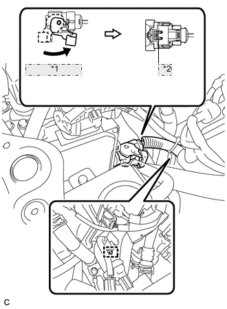
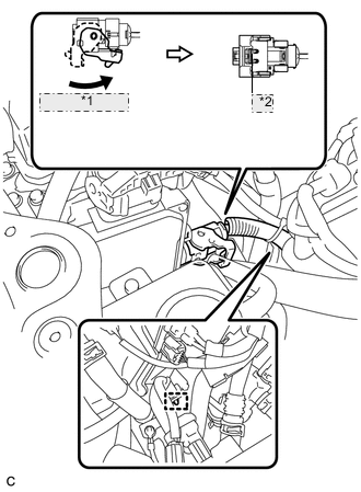
*1 Move the lever *2 Lock the claw Connect the power line connector and securely lock the lock lever as shown in the illustration.
Note
-
Push the connector all the way in and lock the lock lever.
-
Be sure to securely lock the claw of the connector.
Tech Tips
When the connector is pushed all the way in, the lock lever will move slightly to the lock position.
-
-
Install the clamp to the bracket.
-
*1 Push the lock into the connector Push the lock into the connector to securely lock the lock lever of the power line connector.
-
-
Applicable period (2007/12 -)
-
*1 Move the lever *2 Lock the claw Connect the power line connector and securely lock the lock lever as shown in the illustration.
Note
-
Push the connector all the way in and lock the lock lever.
-
Be sure to securely lock the claw of the connector.
Tech Tips
When the connector is pushed all the way in, the lock lever will move slightly to the lock position.
-
-
Install the clamp to the bracket.
-
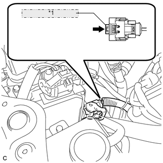
*1 Push the lock into the connector Push the lock into the connector to securely lock the lock lever of the power line connector.
-
-
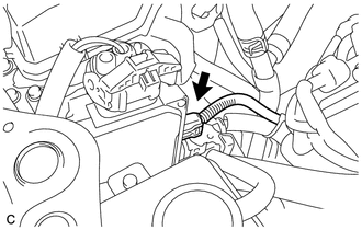
Connect the signal line connector to the oil pump motor controller.
-
-
INSTALL INTAKE AIR CONNECTOR PIPE
-
INSTALL COOL AIR INTAKE DUCT SEAL
-
INSTALL ENGINE ROOM SIDE COVER LH
-
INSTALL ENGINE ROOM SIDE COVER RH
-
INSTALL NO. 1 AIR CLEANER INLET
-
INSTALL AIR CLEANER INLET COVER SUB-ASSEMBLY
-
INSTALL V-BANK COVER SUB-ASSEMBLY
-
CONNECT CABLE TO NEGATIVE BATTERY TERMINAL
Note
When disconnecting the cable, some systems need to be initialized after the cable is reconnected Click here.
-
ADD INVERTER COOLANT (for LHD)
-
INSPECT FOR INVERTER COOLANT LEAK (for LHD)
-
ADD TRANSMISSION FLUID
-
Add transmission fluid Click here.
-
-
B1 AIR BLEEDING
-
Inspect the Control the Shift Position Click here.
-
Connect the intelligent tester to the DLC3.
-
Turn the power switch on (READY) and turn the intelligent tester on.
Note
-
Make sure that the shift lever is in P and the air conditioning is off before turning the power switch on (READY) and turning the intelligent tester on.
-
Make sure that no DTCs are output.
-
Make sure that the transmission fluid temperature is between 0°C and 79°C (32°F to 175°F).
-
-
Enter the following menus: Powertrain / Hybrid Control / Utility / B1 Air Bleeding.
Note
-
Do not move the shift lever from P.
-
Do not turn on the air conditioning while bleeding the air from the B1 chamber.
Tech Tips
It takes about 10 minutes to bleed the air from the B1 chamber.
-
-
Inspect the Control the Shift Position Click here.
-
-
INSTALL NO. 2 ENGINE UNDER COVER
-
INSTALL FRONT CENTER FLOOR COVER (w/ Cover)
-
INSTALL BATTERY SERVICE HOLE COVER LH
-
INSTALL DECK TRIM SIDE BOARD LH (w/o Spare Tire)
-
INSTALL DECK BOARD ASSEMBLY (w/o Spare Tire)
-
INSTALL LUGGAGE COMPARTMENT MAT SUB-ASSEMBLY (w/ Spare Tire)