OIL PUMP MOTOR CONTROLLER INSTALLATION
PROCEDURE
-
INSTALL OIL PUMP MOTOR CONTROLLER
CAUTION:
Be sure to perform the procedure as described below. Do not turn the power switch on (READY) before reconnecting the cable to the negative battery terminal.
-
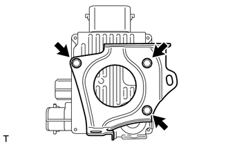
Install the oil pump motor controller with the 3 bolts.
- Torque:
- 6.0 N*m { 61 kgf*cm, 53 in.*lbf }
-
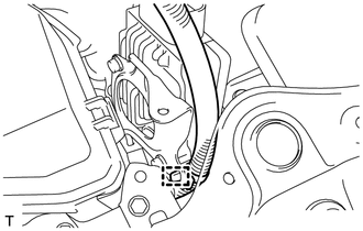
Install the clamp to the bracket.
-
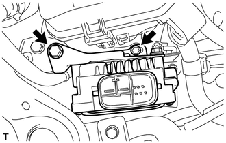
Install the oil pump motor controller with bracket with the 2 bolts.
- Torque:
- 5.0 N*m { 51 kgf*cm, 44 in.*lbf }
-
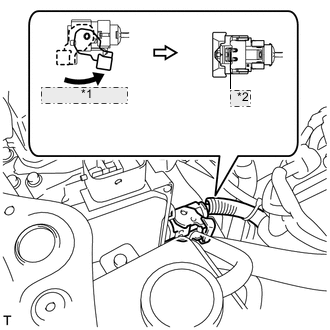
*1 Raise the lever *2 Lock the claw Connect the connector and securely lock the lock lever as shown in the illustration.
Note
-
Be sure to securely lock the claw on the connector.
-
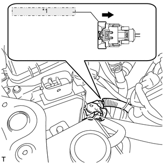
Push the connector all the way in and lock the lock lever.
Tech Tips
When the connector is pushed all the way in, the lock lever will move slightly to the lock position.
-
-
*1 Push in the lever to securely engage the lock Push in the lever to securely engage the lock on the connector.
-
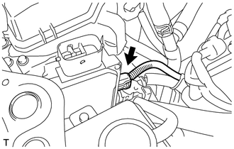
Connect the connector to the oil pump motor controller.
-
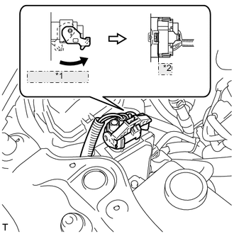
*1 Raise the lever *2 Lock the claw Connect the connector and securely lock the lock lever as shown in the illustration.
Note
-
Be sure to securely lock the claw on the connector.
-
Push the connector all the way in and lock the lock lever.
Tech Tips
When the connector is pushed all the way in, the lock lever will move slightly to the lock position.
-
-
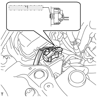
*1 Push the lock into the connector Push the lock into the lock lever to securely lock the lock lever on the connector.
-
-
INSTALL NO. 1 AIR CLEANER INLET
-
INSTALL AIR CLEANER INLET COVER SUB-ASSEMBLY
-
INSTALL ENGINE ROOM SIDE COVER RH
-
INSTALL V-BANK COVER SUB-ASSEMBLY
-
CONNECT CABLE TO NEGATIVE AUXILIARY BATTERY TERMINAL
Note
When disconnecting the cable, some systems need to be initialized after the cable is reconnected Click here.
-
INSTALL BATTERY SERVICE HOLE COVER LH
-
INSTALL DECK TRIM SIDE BOARD LH (w/o Spare Tire)
-
INSTALL DECK BOARD ASSEMBLY (w/o Spare Tire)
-
INSTALL LUGGAGE COMPARTMENT MAT SUB-ASSEMBLY (w/ Spare Tire)