SHIFT LOCK SYSTEM ON-VEHICLE INSPECTION
PROCEDURE
-
CHECK SHIFT LOCK OPERATION
-
Move the shift lever to the P position.
-
Turn the power switch off.
-
Check that the shift lever cannot be moved to any position other than P.
-
Turn the power switch on (IG), depress the brake pedal and check that the shift lever can be moved to other positions.
-
-
CHECK SHIFT LOCK RELEASE BUTTON OPERATION
-
When operating the shift lever with the shift lock release button pressed, check that the lever can be moved to any position other than P.
If the operation cannot be performed as specified, check the shift lever assembly.
-
-
CHECK SHIFT LOCK CONTROL ECU
-
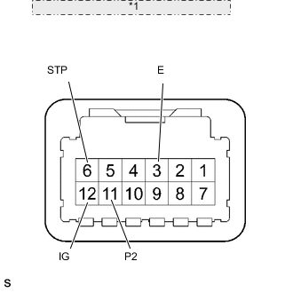
*1 Component with harness connected: (Shift Lock Control ECU) Measure the voltage according to the values in the table below.
Tech Tips
Do not disconnect the shift lock control ECU connector.
Standard voltage Tester Connection Condition Specified Condition 12 (IG) - 3 (E) Power switch on (IG) 10 to 14 V 12 (IG) - 3 (E) Power switch off Below 1 V 6 (STP) - 3 (E) Brake pedal depressed 10 to 14 V 6 (STP) - 3 (E) Brake pedal released Below 1 V 11 (P2) - 3 (E) Shift lever in any position except P 10 to 14 V 11 (P2) - 3 (E) Shift lever in P position Below 1.5 V -
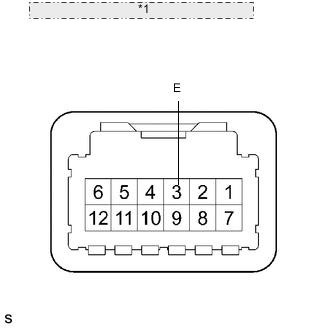
*1 Component with harness connected: (Shift Lock Control ECU) Measure the resistance according to the value in the table below.
Tech Tips
Do not disconnect the shift lock control ECU connector.
Standard resistance Tester Condition Condition Specified Condition 3 (E) - Body ground Always Below 1 Ω If the result is not as specified, replace the transmission floor shift assembly.
-