FRONT DIFFERENTIAL CARRIER ASSEMBLY DISASSEMBLY

PROCEDURE
-
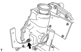
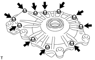
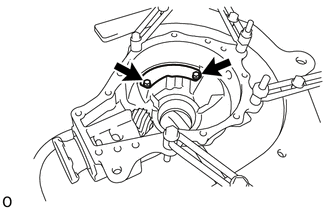
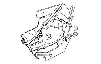
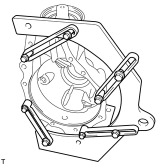
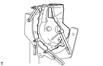
FIX FRONT DIFFERENTIAL CARRIER ASSEMBLY TO OVERHAUL STAND
-
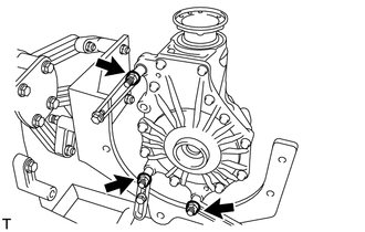
Set the front differential carrier assembly to an overhaul stand as shown in the illustration.
-
-
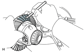
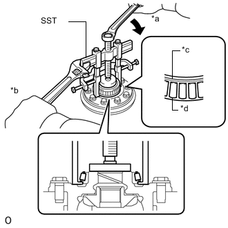
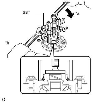
INSPECT DIFFERENTIAL RING GEAR BACKLASH
-
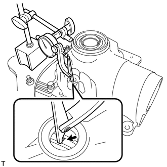
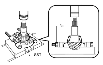
Connect a lever probe to a dial indicator. Insert the probe into the drain plug hole and set it onto the edge of one of the teeth of the differential ring gear at a right angle.
-
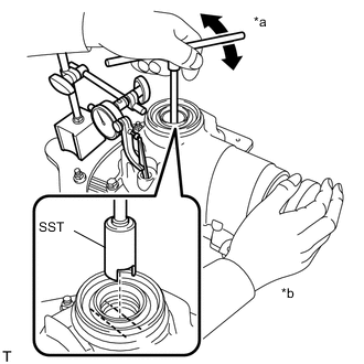
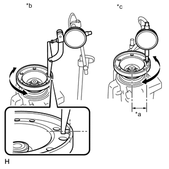
Text in Illustration *a Turn *b Hold Using SST, turn the differential case clockwise and counterclockwise and measure the differential ring gear backlash while holding the companion flange with your hand.
- SST
- 09564-32011
Standard backlash 0.15 to 0.23 mm (0.00591 to 0.00905 in.) Tech Tips
-
Measure at 3 or more areas around the circumference of the differential ring gear.
-
For reassembly purposes, record the result before disassembly.
-
If the backlash is not within the specified range, adjust the differential ring gear backlash or repair as necessary.
-
-
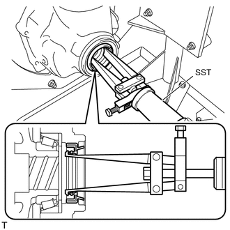
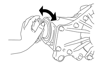
INSPECT RUNOUT OF FRONT DRIVE PINION COMPANION FLANGE FRONT SUB-ASSEMBLY
-
Text in Illustration *a 37 mm (1.46 in.) *b Vertical Runout *c Lateral Runout Wipe the inside surface of the companion flange with a cloth or equivalent and remove dirt and foreign matter.
-
Perform the vertical runout inspection.
-
Connect a lever probe to a dial indicator and set the probe at a right angle to the inner surface of the companion flange.
-
Measure the vertical runout of the companion flange.
Maximum runout 0.12 mm (0.00472 in.)
-
If the runout is more than the maximum value, replace the companion flange.
Tech Tips
For reassembly purposes, record the result before disassembly.
-
-
-
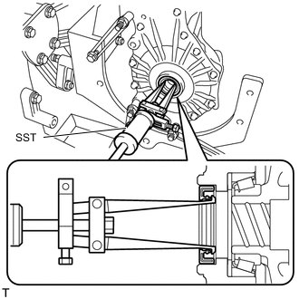
Perform the lateral runout inspection.
-
Set a dial indicator at a right angle to the surface of the companion flange as shown in the illustration.
-
Measure the lateral runout of the companion flange.
Maximum runout 0.08 mm (0.00315 in.)
-
If the runout is more than the maximum value, replace the companion flange.
Tech Tips
For reassembly purposes, record the result before disassembly.
-
-
-
-
REMOVE FRONT DIFFERENTIAL BREATHER PLUG
-
Remove the front differential breather plug from the differential carrier.
-
-
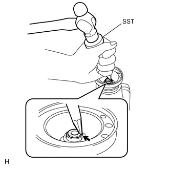
REMOVE FRONT DIFFERENTIAL CASE OIL SEAL
-
Using SST, remove the front differential case oil seal LH from the differential carrier.
- SST
- 09308-00010
-
Using SST, remove the front differential case oil seal RH from the differential carrier.
- SST
- 09308-00010
-
-
REMOVE FRONT DIFFERENTIAL CARRIER RETAINER SUB-ASSEMBLY
-
Loosen the 11 bolts.
-
Remove the front differential carrier assembly from the overhaul attachment.
-
Remove the 11 bolts.
-
Insert the blade of an oil pan seal cutter between the differential carrier and front differential carrier retainer sub-assembly. Cut through the applied seal packing.
Note
Do not damage the installation surface of the differential carrier.
-
Using a brass bar and hammer, lightly tap the front differential carrier retainer sub-assembly to remove it from the differential carrier.
-
-
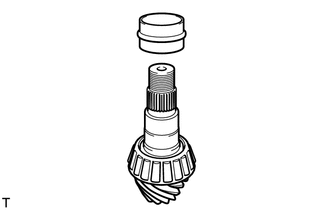
REMOVE NO. 1 FRONT DIFFERENTIAL CASE SUB-ASSEMBLY WITH RING GEAR
-
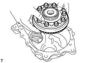
Remove the No. 1 differential case assembly with ring gear from the differential carrier.
Note
Do not damage the 2 front differential case bearings and differential ring gear.
-
-
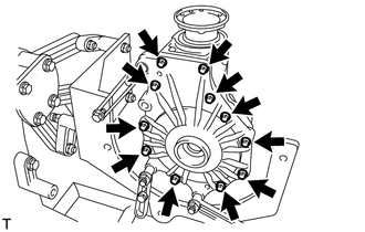
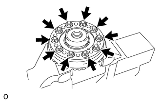
INSPECT TOOTH CONTACT BETWEEN RING GEAR AND DRIVE PINION
-
Uniformly apply a light coat of Prussian blue on both sides of 4 teeth on the differential ring gear.
-
Install the No. 1 front differential case sub-assembly with ring gear to the differential carrier.
-
Install the front differential carrier retainer sub-assembly with the 11 bolts.
- Torque:
- 58 N*m { 591 kgf*cm, 43 ft.*lbf }
-
Rotate the companion flange several times in the forward and backward rotation directions.
-
Remove the 11 bolts and front differential carrier retainer sub-assembly.
-
Remove the No. 1 front differential case sub-assembly with ring gear from the differential carrier.
-
Inspect the tooth contact pattern.
Tech Tips
For reassembly purposes, record the result before disassembly.
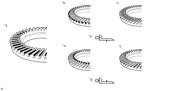
Text in Illustration *a Proper Contact *b Heel Contact *c Face Contact *d Select an adjusting washer that will shift the drive pinion closer to the ring gear (*b, *c) *e Toe Contact *f Flank Contact *g Select an adjusting washer that will shift the drive pinion away from to the ring gear (*e, *f) - -
-
-
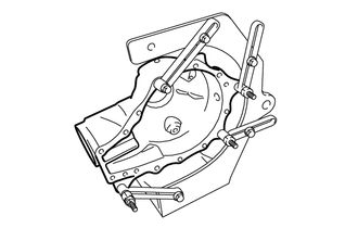
FIX DIFFERENTIAL CARRIER
-
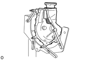
Fix the differential carrier to the overhaul stand.
-
-
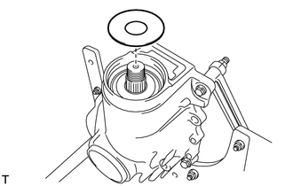
REMOVE FRONT DIFFERENTIAL BREATHER PLUG OIL DEFLECTOR
-
Remove the 2 bolts and front differential breather plug oil deflector.
-
-
REMOVE FRONT DRIVE PINION COMPANION FLANGE FRONT NUT
-
Using SST and a hammer, unstake the staked part of the front drive pinion companion flange front nut.
- SST
- 09930-00010
Note
-
Be sure to use SST with the tapered surface facing the shaft.
-
Do not grind the tip of SST with a grinder etc.
-
Completely loosen the staked part of the nut when removing it.
-
Do not damage the threads of the drive pinion.
-
Text in Illustration *a Turn *b Hold Using SST to hold the flange, remove the front drive pinion companion flange front nut.
- SST
- 09213-58013
- 09229-55010
- 09330-00021
Note
Perform the removal while supporting the overhaul attachment.
-
-
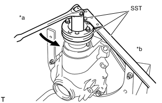
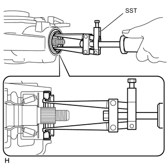
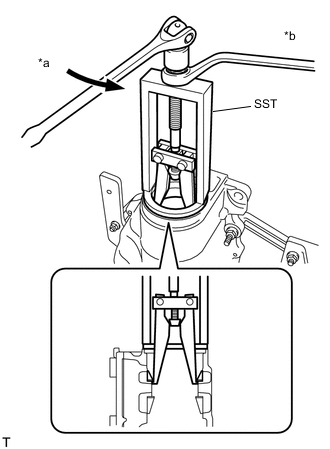
REMOVE FRONT DRIVE PINION COMPANION FLANGE FRONT SUB-ASSEMBLY
-
Text in Illustration *a Center Bolt *b Turn *c Hold Using SST, remove the front drive pinion companion flange front sub-assembly from the differential carrier.
- SST
- 09950-30012 ( 09951-03010, 09953-03010, 09954-03010, 09955-03030, 09956-03020 )
Tech Tips
Before using SST center bolt, apply hypoid gear oil to its threads and tip.
-
-
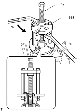
REMOVE FRONT DIFFERENTIAL DUST DEFLECTOR
-
Using SST and a press, press out the front differential dust deflector from the front drive pinion companion flange front sub-assembly.
- SST
- 09950-00020
- 09950-60010 ( 09951-00430 )
- 09950-70010 ( 09951-07100 )
Note
-
Perform this procedure while tightening SST nut to secure the contact surfaces of SST and the front differential dust deflector.
-
Do not drop the front drive pinion companion flange front sub-assembly.
-
-
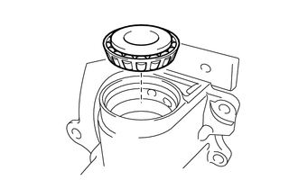
REMOVE FRONT DIFFERENTIAL CARRIER OIL SEAL
-
Using a SST, remove the front differential carrier oil seal from the differential carrier.
- SST
- 09308-00010
-
-
REMOVE FRONT DIFFERENTIAL DRIVE PINION OIL SLINGER
-
Remove the front differential drive pinion oil slinger from the differential carrier.
-
-
REMOVE FRONT DRIVE PINION REAR TAPERED ROLLER BEARING INNER RACE
-
Remove the differential carrier together with the overhaul attachment from the engine stand.
-
Set the differential carrier to an overhaul stand, etc. as shown in the illustration.
-
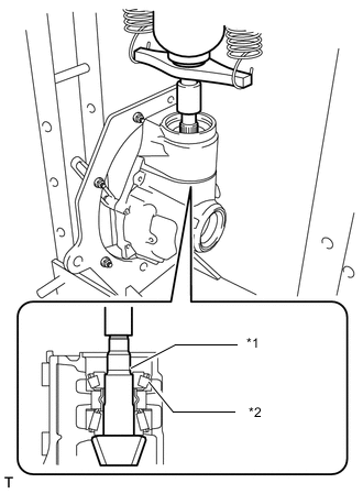
Text in Illustration *1 Differential Drive Pinion *2 Front Drive Pinion Rear Tapered Roller Bearing Inner Race Using a press, press out the differential drive pinion.
Note
Do not drop the differential drive pinion.
-
Remove the front drive pinion rear tapered roller bearing inner race from the differential carrier.
-
Install the differential carrier to the overhaul attachment as it was installed previously.
-
Install the differential carrier together with overhaul attachment to the engine stand.
-
-
REMOVE FRONT DIFFERENTIAL DRIVE PINION BEARING SPACER
-
Remove the front differential drive pinion bearing spacer from the differential drive pinion.
-
-
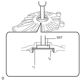
REMOVE FRONT DRIVE PINION FRONT TAPERED ROLLER BEARING INNER RACE
-
Text in Illustration *a Nut Using SST and a press, remove the front drive pinion front tapered roller bearing inner race from the differential drive pinion.
- SST
- 09950-00020
Note
Do not drop the differential drive pinion.
Tech Tips
Perform this procedure while tightening SST nut to secure the contact surfaces of SST and the front drive pinion front tapered roller bearing inner race.
If either the differential drive pinion or the differential ring gear is damaged, replace both as a set.
-
-
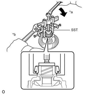
REMOVE FRONT DRIVE PINION REAR TAPERED ROLLER BEARING OUTER RACE
-
Text in Illustration *a Turn *b Hold Using SST, remove the front drive pinion rear tapered roller bearing outer race from the differential carrier.
- SST
- 09387-00041 ( 09387-02020 )
-
-
REMOVE FRONT DRIVE PINION FRONT TAPERED ROLLER BEARING OUTER RACE
-
Text in Illustration *1 Front Drive Pinion Spacer Adjust Shim Using SST and a hammer, tap out the front drive pinion front tapered roller bearing outer race and front drive pinion spacer adjust shim from the differential carrier.
- SST
- 09950-70010 ( 09951-07150 )
- 09950-60010 ( 09951-00610, 09951-00650, 09952-06010 )
Tech Tips
For reassembly purposes, measure the thickness of the front drive pinion spacer adjust shim, and record the result.
-
-
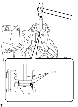
REMOVE FRONT DIFFERENTIAL CASE BEARING LH
-
Text in Illustration *1 Differential Case Washer *2 Front Differential Case Bearing LH (Outer Race) Using SST and a press, press out the front differential case bearing LH (outer race) and differential case washer from the differential carrier.
- SST
- 09950-60010 ( 09951-00510, 09952-06010 )
- 09950-60020 ( 09951-00680 )
- 09950-70010 ( 09951-07100 )
-
-
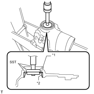
REMOVE FRONT DIFFERENTIAL CASE BEARING RH
-
Text in Illustration *1 Differential Case Washer *2 Front Differential Case Bearing RH (Outer Race) Using SST and a press, press out the front differential case bearing RH (outer race) and differential case washer from the front differential carrier retainer sub-assembly.
- SST
- 09950-60010 ( 09951-00520 )
- 09950-70010 ( 09951-07100 )
-
-
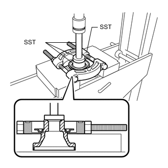
REMOVE FRONT DIFFERENTIAL CASE BEARING LH
-
Text in Illustration *a Turn *b Hold Using SST, remove the front differential case bearing LH (inner race) from the No. 1 front differential case sub-assembly with ring gear.
- SST
- 09950-40011 ( 09951-04020, 09952-04010, 09953-04030, 09954-04010, 09955-04051, 09957-04010, 09958-04011 )
- 09950-60010 ( 09951-00460 )
Note
Before using SST center bolt (09953-04030), apply oil to its threads and tip.
-
-
REMOVE FRONT DIFFERENTIAL CASE BEARING RH
-
Text in Illustration *a Turn *b Hold *c Roller Cage *d Roller Using SST, remove the roller cage and bearing rollers.
- SST
- 09950-40011 ( 09951-04020, 09952-04010, 09953-04030, 09954-04010, 09955-04011, 09957-04010, 09958-04011 )
- 09950-60010 ( 09951-00510 )
Note
Before using SST center bolt (09953-04030), apply oil to its threads and tip.
-
Text in Illustration *a Turn *b Hold Using SST, remove the race from the No. 1 front differential case sub-assembly with ring gear.
- SST
- 09950-40011 ( 09951-04020, 09952-04010, 09953-04030, 09954-04010, 09955-04011, 09957-04010, 09958-04011 )
- 09950-60010 ( 09951-00510 )
Note
Before using SST center bolt (09953-04030), apply oil to its threads and tip.
-
-
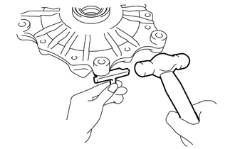
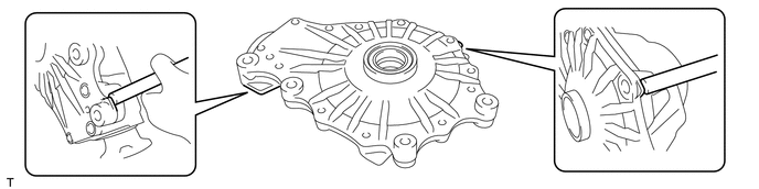
REMOVE DIFFERENTIAL RING GEAR
-
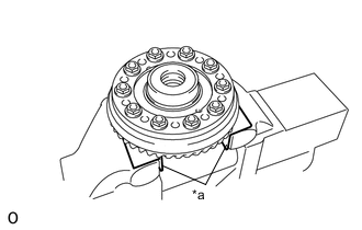
Text in Illustration *a Aluminum Plate Hold the differential case in a vise between aluminum plates.
Note
Do not overtighten the vise.
-
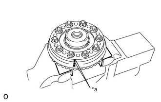
Text in Illustration *a Matchmark Put matchmarks on the differential ring gear and No. 1 front differential case sub-assembly.
-
Remove the 10 differential ring gear set bolts.
-
Remove the differential case from the vise.
-
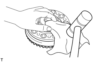
Using a plastic-faced hammer, tap on the differential ring gear to separate it from the No. 1 front differential case sub-assembly.
Tech Tips
Place a cloth on the tooth side of the differential ring gear to prevent damage.
-