HYBRID BATTERY SYSTEM, Diagnostic DTC:P0A84-123
| DTC Code | DTC Name |
|---|---|
| P0A84-123 | Hybrid Battery Pack Cooling Fan 1 |
DESCRIPTION
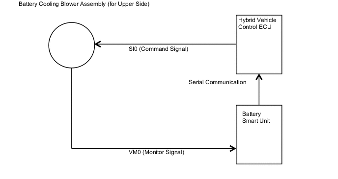
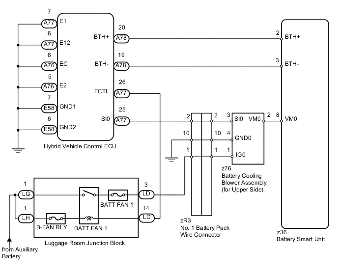
The speed of the battery cooling blower assembly (for upper side) is controlled by the hybrid vehicle control ECU in accordance with the HV battery temperature and SOC. Battery cooling blower assembly (for upper side) power is supplied when the FCTL terminal of the hybrid vehicle control ECU turns on the BATT FAN 1 relay. The hybrid vehicle control ECU sends command signals (SI0) to the battery cooling blower assembly (for upper side) to achieve the fan speed that corresponds to the HV battery temperature. Voltage (VM0) from the battery cooling blower assembly (for upper side) is used to monitor the operation of the battery cooling blower assembly (for upper side). The voltage is sent from the battery cooling blower assembly (for upper side) to the hybrid vehicle control ECU via the battery smart unit. Between the battery smart unit and the hybrid vehicle control ECU, serial communication is used.
| DTC Code | DTC Detection Condition | Trouble Area |
|---|---|---|
| P0A84-123 | The output voltage of the battery cooling blower assembly (for upper side) (VM0) is lower than the target control voltage range when the battery cooling blower assembly (for upper side) is activated. (1 trip detection) |
|
WIRING DIAGRAM
CAUTION:
-
Before inspecting the high-voltage system, take safety precautions such as wearing insulated gloves and removing the service plug grip to prevent electrical shocks. After removing the service plug grip, put it in your pocket to prevent other technicians from accidentally reconnecting it while you are working on the high-voltage system.
-
After disconnecting the service plug grip, wait for at least 10 minutes before touching any of the high-voltage connectors or terminals. After waiting for 10 minutes, check the voltage at the terminals in the inspection point in the inverter with converter assembly. The voltage should be 0 V before beginning work.
Tech Tips
Waiting for at least 10 minutes is required to discharge the high-voltage capacitor inside the inverter with converter assembly.
PROCEDURE
-
CHECK FOR DTCS (DTC P0AFC-123 IS OUTPUT)
-
Connect the intelligent tester to the DLC3.
-
Turn the power switch on (IG).
-
Select the following menu items: Powertrain / Hybrid Control / Trouble Codes.
-
Check if DTCs are output.
Result Result Proceed to P0AFC-123 is not output. A P0AFC-123 is output. B
B 
GO TO DTC (P0AFC-123) Click here
A 
-
-
CHECK FUSES (BATT FAN 1 AND B-FAN RLY)
-
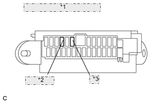
*1 Luggage Room Junction Block *2 BATT FAN 1 *3 B-FAN RLY Turn the power switch off.
-
Remove the BATT FAN 1 fuse and B-FAN RLY fuse from the luggage room junction block.
-
Measure the resistance according to the value(s) in the table below.
Standard Resistance Tester Connection Condition Specified Condition BATT FAN 1 fuse Always Below 1 Ω B-FAN RLY fuse Always Below 1 Ω
NG
REPLACE FUSE (BATT FAN 1 OR B-FAN RLY)
OK
-
-
CHECK HARNESS AND CONNECTOR (NO. 1 BATTERY PACK WIRE CONNECTOR [B SIDE] - BATTERY)
-
Install the BATT FAN 1 fuse and B-FAN RLY fuse.
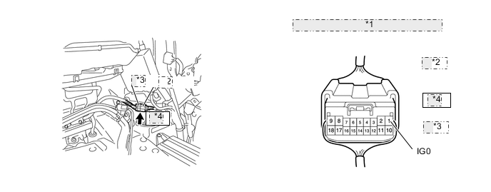
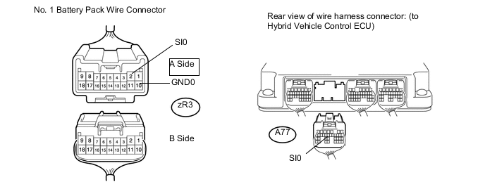
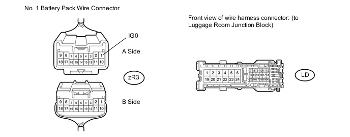
*1 No. 1 Battery Pack Wire Connector *2 A Side *3 B Side *4 zR3 -
Turn the power switch on (IG).
-
Measure the voltage according to the value(s) in the table below.
Standard Voltage Tester Connection Switch Condition Specified Condition zR3-1 (IG0) - Body ground Power switch on (IG) 11 to 14 V Tech Tips
-
For the removal and installation procedures related to the No. 1 battery pack wire connector inspection, Click here.
-
Perform this inspection with the No. 1 battery pack wire connector connected.
-
NG 
INSPECT LUGGAGE ROOM JUNCTION BLOCK (BATT FAN 1 RELAY) Click here
OK
-
-
CHECK HARNESS AND CONNECTOR (NO. 1 BATTERY PACK WIRE CONNECTOR [A SIDE] - HYBRID VEHICLE CONTROL ECU)
-
Disconnect the zR3 No. 1 battery pack wire connector.
Tech Tips
For the removal and installation procedures related to the No. 1 battery pack wire connector inspection, Click here.
-
Disconnect the A77 hybrid vehicle control ECU connector.
-
Measure the resistance according to the value(s) in the table below.
Standard Resistance (Check for open) Tester Connection Switch Condition Specified Condition zR3-2 (SI0) - A77-25 (SI0) Power switch off Below 1 Ω zR3-10 (GND0) - Body ground Power switch off Below 1 Ω Standard Resistance (Check for short) Tester Connection Switch Condition Specified Condition zR3-2 (SI0) - Body ground and other terminals Power switch off 10 kΩ or higher -
Turn the power switch on (IG).
-
Measure the voltage according to the value(s) in the table below.
Standard Voltage (Check for +B short) Tester Connection Switch Condition Specified Condition zR3-2 (SI0) - Body ground Power switch on (IG) Below 1 V Tech Tips
If the power switch is turned on (IG) under the conditions above, DTCs may be stored. In this case, use the intelligent tester to clear the DTCs Click here.
NG
REPAIR OR REPLACE HARNESS OR CONNECTOR
OK
-
-
CHECK HARNESS AND CONNECTOR (NO. 1 BATTERY PACK WIRE CONNECTOR [B SIDE] - BATTERY COOLING BLOWER [FOR UPPER SIDE])
CAUTION:
Be sure to wear insulated gloves.
-
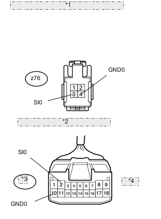
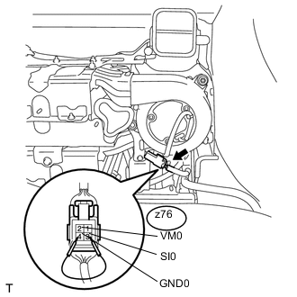
*1 Front view of wire harness connector: (to Battery Cooling Blower Assembly [for Upper Side]) *2 No. 1 Battery Pack Wire Connector *3 zR3 *4 B Side Remove the HV battery Click here.
-
Disconnect the z76 battery cooling blower assembly (for upper side) connector.
Tech Tips
For the removal and installation procedures related to the battery cooling blower assembly (for upper side) connector inspection, Click here.
-
Measure the resistance according to the value(s) in the table below.
Standard Resistance Tester Connection Condition Specified Condition zR3-2 (SI0) - z76-3 (SI0) Always Below 1 Ω zR3-10 (GND0) - z76-4 (GND0) Always Below 1 Ω
NG
REPAIR OR REPLACE HARNESS OR CONNECTOR
OK
-
-
CHECK HARNESS AND CONNECTOR (NO. 1 BATTERY PACK WIRE CONNECTOR [B SIDE] - BATTERY COOLING BLOWER [FOR UPPER SIDE])
CAUTION:
Be sure to wear insulated gloves.
-
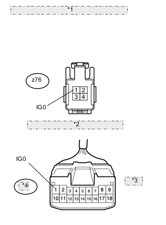
*1 Front view of wire harness connector: (to Battery Cooling Blower Assembly [for Upper Side]) *2 No. 1 Battery Pack Wire Connector *3 B Side *4 zR3 Measure the resistance according to the value(s) in the table below.
Standard Resistance Tester Connection Condition Specified Condition zR3-1 (IG0) - z76-1 (IG0) Always Below 1 Ω
NG
REPAIR OR REPLACE HARNESS OR CONNECTOR
OK
-
-
CHECK HARNESS AND CONNECTOR (BATTERY COOLING BLOWER [FOR UPPER SIDE] - BATTERY SMART UNIT)
CAUTION:
Be sure to wear insulated gloves.
-
Disconnect the z36 battery smart unit connector.
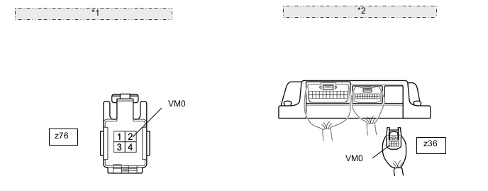
*1 Front view of wire harness connector: (to Battery Cooling Blower Assembly [for Upper Side]) *2 Rear view of wire harness connector: (to Battery Smart Unit) Tech Tips
For the removal and installation procedures related to the battery smart unit connector inspection, Click here.
-
Measure the resistance according to the value(s) in the table below.
Standard Resistance (Check for open) Tester Connection Condition Specified Condition z76-2 (VM0) - z36-8 (VM0) Always Below 1 Ω Standard Resistance (Check for short) Tester Connection Condition Specified Condition z76-2 (VM0) - Body ground and other terminals Always 10 kΩ or higher
NG
REPAIR OR REPLACE HARNESS OR CONNECTOR
OK
-
-
CHECK BATTERY COOLING BLOWER ASSEMBLY (for Upper Side) (VM0 VOLTAGE)
CAUTION:
Be sure to wear insulated gloves.
-
Place the HV battery in the vehicle so that measurements can be made at the battery cooling blower assembly (for upper side) connector.
Note
Make sure all the covers are installed to the HV battery when placing it in the vehicle, and then remove the covers again after the HV battery is in place.
Tech Tips
-
Follow the installation procedures to the point where the HV battery is set in the vehicle Click here.
-
Do not install the service plug grip.
-
-
Reconnect all the connectors that were disconnected when the HV battery was removed.
-
Connect the intelligent tester to the DLC3.
-
Turn the power switch on (IG).
-
Select the following menu items: Powertrain / Hybrid Control / Data List / VMF Fan Motor Voltage 1.
-
Using a service wire, connect terminals z76-3 (SI0) and z76-4 (GND0) of the battery cooling blower assembly (for upper side) connector.
-
While the battery cooling blower assembly (for upper side) is operating, compare the value in the data list ("VMF Fan Motor Voltage 1") with the voltage value that was actually measured at the battery cooling blower assembly (for upper side) connector.
Result Tester Connection Switch Condition Result Proceed to z76-2 (VM0) - z76-4 (GND0) Power switch on (IG) The difference between the value in the Data List ("VMF Fan Motor Voltage 1") and the actual measurement value is 1 V or higher. A The difference between the value in the Data List ("VMF Fan Motor Voltage 1") and the actual measurement value is below 1 V and the value in the Data List ("VMF Fan Motor Voltage 1") is 0.6 V or less. B The difference between the value in the Data List ("VMF Fan Motor Voltage 1") and the actual measurement value is below 1 V and the value in the Data List ("VMF Fan Motor Voltage 1") is higher than 0.6 V. C Tech Tips
-
Perform this inspection with the battery cooling blower assembly (for upper side) connector connected.
-
If the power switch is turned on (IG) with the service plug grip removed, DTC P0A0D-350 for the interlock switch system will be set. If this DTC is output, clear the DTC using the intelligent tester Click here.
-
A
REPLACE BATTERY SMART UNIT Click here
B
REPLACE BATTERY COOLING BLOWER ASSEMBLY (for Upper Side) Click here
C
REPLACE HYBRID VEHICLE CONTROL ECU Click here
-
-
INSPECT LUGGAGE ROOM JUNCTION BLOCK (BATT FAN 1 RELAY)
-
Install the BATT FAN 1 fuse and B-FAN RLY fuse.
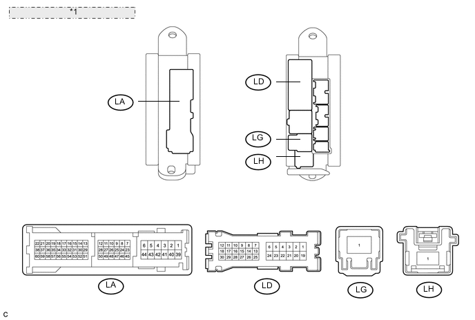
*1 Luggage Room Junction Block (Built-in BATT FAN 1 relay) -
Remove the luggage room junction block.
-
Measure the resistance according to the value(s) in the table below.
Tech Tips
The BATT FAN 1 relay is located inside the luggage room junction block.
Standard Resistance Tester Connection Condition Specified Condition LG-1 - LD-3 Battery voltage is not applied between terminals LH-1 and LD-14. 10 kΩ or higher LG-1 - LD-3 Battery voltage is applied between terminals LH-1 and LD-14. Below 1 Ω
NG
REPLACE LUGGAGE ROOM JUNCTION BLOCK (BATT FAN 1 RELAY)
OK
-
-
CHECK HARNESS AND CONNECTOR (LUGGAGE ROOM JUNCTION BLOCK - HYBRID VEHICLE CONTROL ECU)
-
Disconnect the A77 hybrid vehicle control ECU connector.
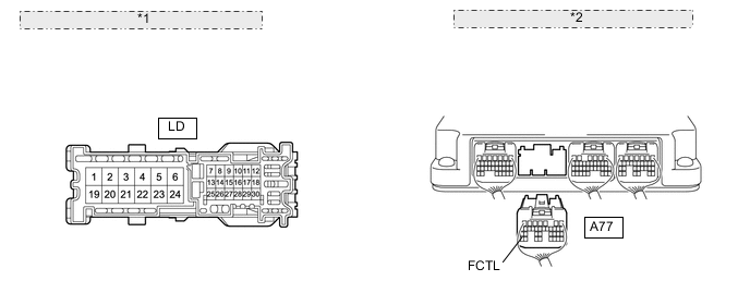
*1 Front view of wire harness connector: (to Luggage Room Junction Block) *2 Rear view of wire harness connector: (to Hybrid Vehicle Control ECU) -
Disconnect the LD luggage room junction block connector.
-
Measure the resistance according to the value(s) in the table below.
Standard Resistance (Check for open) Tester Connection Switch Condition Specified Condition LD-14 - A77-26 (FCTL) Power switch off Below 1 Ω Standard Resistance (Check for short) Tester Connection Switch Condition Specified Condition LD-14 or A77-26 (FCTL) - Body ground and other terminals Power switch off 10 kΩ or higher Note
When taking measurements with an electrical tester, do not apply excessive force to the tester probes to avoid damaging the terminals.
-
Turn the power switch on (IG).
-
Measure the voltage according to the value(s) in the table below.
Standard Voltage (Check for +B short) Tester Connection Switch Condition Specified Condition A77-26 (FCTL) - Body ground Power switch on (IG) Below 1 V Tech Tips
If the power switch is turned on (IG) under the conditions above, DTCs may be stored. In this case, use the intelligent tester to clear the DTCs Click here.
NG
REPAIR OR REPLACE HARNESS OR CONNECTOR
OK
-
-
CHECK HARNESS AND CONNECTOR (LUGGAGE ROOM JUNCTION BLOCK - NO. 1 BATTERY PACK WIRE CONNECTOR [A SIDE])
-
Disconnect the zR3 No. 1 battery pack wire connector.
-
Disconnect the LD luggage room junction block connector.
-
Measure the resistance according to the value(s) in the table below.
Standard Resistance (Check for open) Tester Connection Switch Condition Specified Condition LD-3 - zR3-1 (IG0) Power switch off Below 1 Ω Standard resistance (Check for short) Tester Connection Switch Condition Specified Condition LD-3 or zR3-1 (IG0) - Body ground and other terminals Power switch off 10 kΩ or higher Note
When taking measurements with an electrical tester, do not apply excessive force to the tester probes to avoid damaging the terminals.
OK
REPLACE HYBRID VEHICLE CONTROL ECU Click here
NG
REPAIR OR REPLACE HARNESS OR CONNECTOR
-