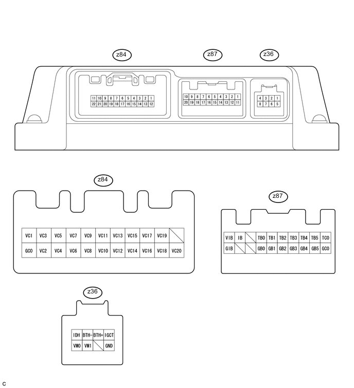
HYBRID BATTERY SYSTEM TERMINALS OF ECU
-
CHECK BATTERY SMART UNIT
-
Measure the voltage and resistance according to the value(s) in the table below.
Symbols
(Terminal No.)
Wiring Color Terminal Description Condition Standard Value (Reference Value) z87-1 (TC0) - z87-11 (GC0) G - G Intake air temperature sensor Intake air temperature: -40 to 90°C (-40 to 194°F) 4.8 (-40°C [-40°F]) to 1.0 V(90°C [194°F]) z87-2 (TB5) - z87-12 (GB5) W - W HV battery temperature sensor 5 HV battery temperature: -40 to 90°C (-40 to 194°F) 4.8 (-40°C [-40°F]) to 1.0 V(90°C [194°F]) z87-3 (TB4) - z87-13 (GB4) R - R HV battery temperature sensor 4 HV battery temperature: -40 to 90°C (-40 to 194°F) 4.8 (-40°C [-40°F]) to 1.0 V(90°C [194°F]) z87-4 (TB3) - z87-14 (GB3) L - L HV battery temperature sensor 3 HV battery temperature: -40 to 90°C (-40 to 194°F) 4.8 (-40°C [-40°F]) to 1.0 V(90°C [194°F]) z87-5 (TB2) - z87-15 (GB2) R - R HV battery temperature sensor 2 HV battery temperature: -40 to 90°C (-40 to 194°F) 4.8 (-40°C [-40°F]) to 1.0 V(90°C [194°F]) z87-6 (TB1) - z87-16 (GB1) W - W HV battery temperature sensor 1 HV battery temperature: -40 to 90°C (-40 to 194°F) 4.8 (-40°C [-40°F]) to 1.0 V(90°C [194°F]) z87-7 (TB0) - z87-17 (GB0) B - B HV battery temperature sensor 0 HV battery temperature: -40 to 90°C (-40 to 194°F) 4.8 (-40°C [-40°F]) to 1.0 V(90°C [194°F]) z87-9 (IB) - z87-20 (GIB) W - B Battery current sensor Power switch on (READY) 0.5 to 4.5 V z87-10 (VIB) - z87-20 (GIB) R - B Power source for battery current sensor Power switch on (IG) 4.5 to 5.5 V z36-1 (IGCT) - z36-5 (GND) L - W-B Control signal Power switch on (READY) 11 to 15.5 V z36-2 (BTH+) - z36-5 (GND) R - W-B Serial communication Power switch on (IG) Pulse generation
(Waveform 1)
z36-3 (BTH-) - z36-5 (GND) G - W-B Serial communication Power switch on (IG) Pulse generation
(Waveform 2)
z36-4 (IDH) - z36-5 (GND) P - W-B Hybrid vehicle converter cooling fan signal Power switch on (IG) Pulse generation
(Waveform 3)
z36-7 (VM1) - z36-5 (GND) BR - W-B Battery cooling blower assembly (for lower side) monitor signal Battery cooling blower assembly (for lower side) not activated 0 V z36-7 (VM1) - z36-5 (GND) BR - W-B Battery cooling blower assembly (for lower side) monitor signal Battery cooling blower assembly (for lower side) activated 0 to 5 V z36-8 (VM0) - z36-5 (GND) LG - W-B Battery cooling blower assembly (for upper side) monitor signal Battery cooling blower assembly (for upper side) not activated 0 V z36-8 (VM0) - z36-5 (GND) LG - W-B Battery cooling blower assembly (for upper side) monitor signal Battery cooling blower assembly (for upper side) activated 0 to 5 V z36-5 (GND) - Body ground W-B - Body ground Ground Always (continuity check) Below 6 Ω If the result is not as specified, the battery smart unit may have a malfunction.
-
Oscilloscope waveforms
Tech Tips
Oscilloscope waveform samples are provided here for informational purposes. Noise and fluttering waveforms have been omitted.
-
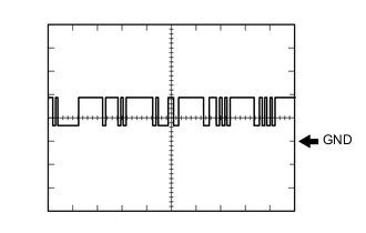
Waveform 1
Item Contents Terminal z36-2 (BTH+) - z36-5 (GND) Equipment Setting 2 V/DIV, 500 μs/DIV Condition Power switch on (IG) Tech Tips
The waveform will vary depending on the content of the digital communication (digital signal).
-
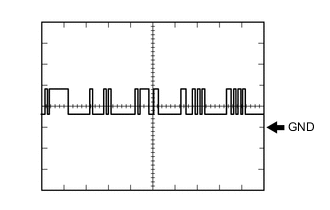
Waveform 2
Item Contents Terminal z36-3 (BTH-) - z36-5 (GND) Equipment Setting 2 V/DIV, 500 μs/DIV Condition Power switch on (IG) Tech Tips
The waveform will vary depending on the content of the digital communication (digital signal).
-
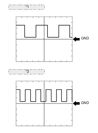
*1 Operating Condition 1 *2 Operating Condition 6 Waveform 3
Item Contents Terminal z36-4 (IDH) - z36-5 (GND) Equipment Setting 2 V/DIV, 2 ms/DIV Condition Power switch on (IG) Tech Tips
The frequency of the waveform differs according to operation conditions of the cooling fan of the hybrid vehicle converter.
-
-