HYBRID CONTROL SYSTEM, Diagnostic DTC:P3110-139
| DTC Code | DTC Name |
|---|---|
| P3110-139 | HV Main Relay |
DESCRIPTION
The hybrid vehicle control ECU monitors the ST CUT/IGCT2 relay and detects the following malfunction.
| DTC No. | INF Code | DTC Detection Condition | Trouble Area |
|---|---|---|---|
| P3110 | 139 | Short to +B in the ST CUT/IGCT2 relay drive signal circuit |
|
WIRING DIAGRAM
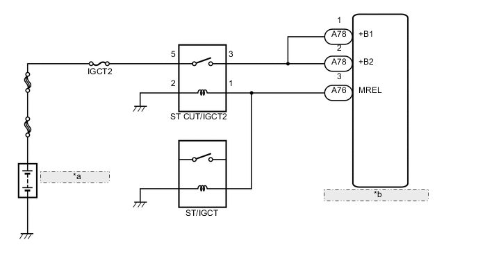
| *a | Auxiliary Battery |
| *b | Hybrid Vehicle Control ECU |
CAUTION / NOTICE / HINT
Tech Tips
If battery voltage is applied to terminal MREL of the hybrid vehicle control ECU, even though the power switch is off, +B power source voltage will be applied to terminals +B and +B2 of the hybrid vehicle control ECU.
PROCEDURE
-
CHECK HARNESS AND CONNECTOR (HYBRID VEHICLE CONTROL ECU - ENGINE ROOM NO. 2 RELAY BLOCK)
-
Disconnect connector A76 from the hybrid vehicle control ECU.
-
Turn the power switch on (IG).
-
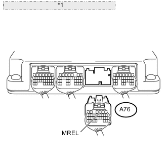
*1 Rear view of wire harness connector: (to Hybrid Vehicle Control ECU) Measure the voltage according to the value(s) in the table below.
Note
Turning the power switch on (IG) with the hybrid vehicle control ECU connector disconnected causes other DTCs to be stored. Clear the DTCs after performing this inspection.
Standard voltage Tester Connection Switch Condition Specified Condition A76-3 (MREL) - Body ground Power switch on (IG) Below 1 V
OK 
REPLACE HYBRID VEHICLE CONTROL ECU Click here
NG 
-
-
CHECK RELAY (ST CUT/IGCT2 RELAY)
-
Turn the power switch off.
-
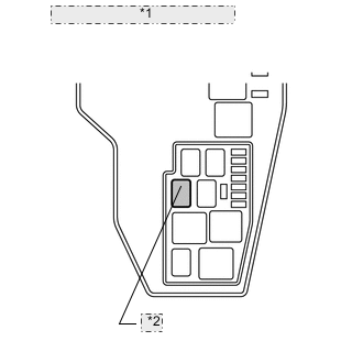
*1 Engine Room No. 2 Relay Block *2 ST CUT/IGCT2 Relay Remove the ST CUT/IGCT2 relay from the engine room No. 2 relay block.
-
Measure the resistance according to the value(s) in the table below.
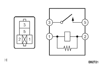
Standard resistance Tester Connection Condition Specified Condition 1 - 2 Always Below 1 Ω 3 - 5 Battery voltage is not applied between terminals 1 and 2. 10 kΩ or higher Battery voltage is applied between terminals 1 and 2. Below 1 Ω
NG
REPLACE RELAY (ST CUT/IGCT2 RELAY)
OK
-
-
CHECK RELAY (ST/IGCT RELAY)
-
Turn the power switch off.
-
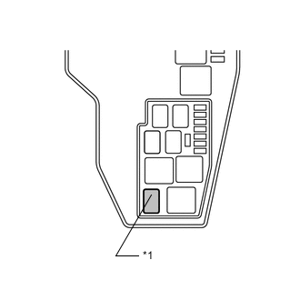
*1 ST/IGCT Relay Remove the ST/IGCT relay from the engine room No. 2 relay block.
-
Measure the resistance according to the value(s) in the table below.
Standard resistance Tester Connection Condition Specified Condition 1 - 2 Always Below 1 Ω 3 - 5 Battery voltage is not applied between terminals 1 and 2. 10 kΩ or higher Battery voltage is applied between terminals 1 and 2. Below 1 Ω
OK
REPAIR OR REPLACE HARNESS OR CONNECTOR
NG
REPLACE RELAY (ST/IGCT RELAY)
-