HYBRID CONTROL SYSTEM, Diagnostic DTC:P3004-131
| DTC Code | DTC Name |
|---|---|
| P3004-131 | Power Cable Malfunction |
DESCRIPTION
Refer to the description for DTC P0AE6-225 Click here.
The hybrid vehicle control ECU monitors the high-voltage wiring between the HV battery and the inverter with converter assembly and detects malfunctions.
| DTC No. | INF Code | DTC Detection Condition | Trouble Area |
|---|---|---|---|
| P3004 | 131 | The inverter voltage does not rise during precharge (time from when SMRP turns on until SMRG turns on). |
|
CAUTION / NOTICE / HINT
CAUTION:
-
Before inspecting the high-voltage system or disconnecting the low voltage connector of the inverter with converter assembly, take safety precautions such as wearing insulated gloves and removing the service plug grip to prevent electrical shocks. After removing the service plug grip, put it in your pocket to prevent other technicians from accidentally reconnecting it while you are working on the high-voltage system.
-
After disconnecting the service plug grip, wait for at least 10 minutes before touching any of the high-voltage connectors or terminals. After waiting for 10 minutes, check the voltage at the terminals in the inspection point in the inverter with converter assembly. The voltage should be 0 V before beginning work.
Tech Tips
Waiting for at least 10 minutes is required to discharge the high-voltage capacitor inside the inverter with converter assembly.
PROCEDURE
-
CHECK DTC OUTPUT (HV)
-
Connect the intelligent tester to the DLC3.
-
Turn the power switch on (IG).
-
Select the following menu items: Powertrain / Hybrid Control / Trouble Codes.
-
Check if DTCs are output.
Result Result Proceed to P3004-131 only is output. A Any of the following DTCs are also output. B DTC No. Relevant Diagnosis P0A1A-151, 155, 156, 658, 659 Generator Control Module P0A1B-163, 164, 193, 511, 512, 661, 786, 788 Drive Motor "A" Control Module P0A78-266, 267, 586 Drive Motor "A" Inverter Performance P0A94-442 DC / DC Converter Performance P0A95-123 High Voltage Fuse P0ABF-123 Hybrid Battery Pack Current Sensor Circuit P0AC0-123 Hybrid Battery Pack Current Sensor Circuit Range / Performance P0AC1-123 Hybrid Battery Pack Current Sensor Circuit Low P0AC2-123 Hybrid Battery Pack Current Sensor Circuit High P0ADB-227 Hybrid Battery Positive Contactor Control Circuit Low P0ADC-226 Hybrid Battery Positive Contactor Control Circuit High P0AE6-225 Hybrid Battery Precharge Contactor Control Circuit Low P0AE7-224 Hybrid Battery Precharge Contactor Control Circuit High P0AFA-123 Hybrid Battery System Voltage Low P0AFC (all INF codes) *1 Hybrid Battery Pack Sensor Module P0C76-523 Hybrid Battery System Discharge Time Too Long P3004-800, 801 Power Cable Malfunction P3240-443 DC / DC Converter Control Circuit U029A-123 Lost Communication with Hybrid Battery Pack Sensor Module Tech Tips
-
*1: If any INF codes are output for this DTC, refer to the corresponding diagnostic flowchart.
-
P3004-131 may be set due to a malfunction which also causes DTCs in the preceding table to be set. In this case, first troubleshoot the output DTCs in the preceding table. Then, perform a test to attempt to reproduce the problems, and check that no DTCs are output.
-
B 
GO TO DTC CHART Click here
A 
-
-
CHECK FREEZE FRAME DATA
-
Select the following menu items: Powertrain / Hybrid Control / Trouble Codes.
-
Read the freeze frame data of DTC P3004-131.
Result Result Proceed to Both of the following conditions are met:
-
Post-boost voltage (VH-Voltage after Boosting) is below 50 V.
-
Difference between HV battery voltage (Power Resource VB) and pre-boost voltage (VL-Voltage before Boosting) is 50 V or less.
A
(for LHD)
B
(for RHD)
Other than above C -
A
REPLACE INVERTER WITH CONVERTER ASSEMBLY Click here
B
REPLACE INVERTER WITH CONVERTER ASSEMBLY Click here
C
-
-
CHECK CONNECTOR CONNECTION CONDITION (HYBRID VEHICLE CONTROL ECU CONNECTOR)
-
Check the connections of the hybrid vehicle control ECU connectors.
OK The connectors are connected securely and there are no contact problems.
NG
CONNECT SECURELY
OK
-
-
CHECK CONDITION OF FRAME WIRE CONNECTION(S) (INVERTER WITH CONVERTER ASSEMBLY SIDE)
CAUTION:
Be sure to wear insulated gloves.
-
Turn the power switch off.
-
Remove the service plug grip Click here.
Note
After removing the service plug grip, do not turn the power switch on (READY) unless instructed by the repair manual because this may cause a malfunction.
-
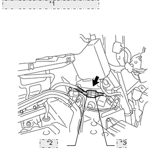
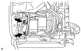
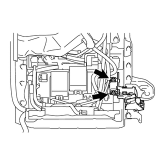
Remove the connector cover from the inverter with converter assembly.
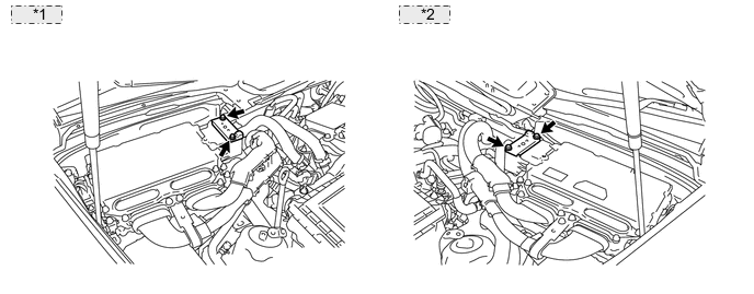
*1 for LHD: *2 for RHD: -
Check the connection between the frame wire and the inverter with converter assembly.
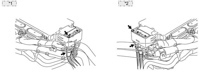
*1 for LHD: *2 for RHD: OK The connectors are connected securely and there are no contact problems.
NG
CONNECT SECURELY
OK
-
-
CHECK CONDITION OF FRAME WIRE CONNECTION(S) (HV BATTERY JUNCTION BLOCK SIDE)
CAUTION:
Be sure to wear insulated gloves.
-
Check that the service plug grip is not installed.
-
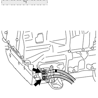
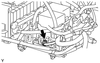
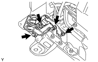
*1 Frame Wire (HV Battery Junction Block Side) Check the connection between the frame wire and the HV battery junction block.
Specified Condition T=9.0 N*m {92 kgf*cm, 80 in.*lbf} Tech Tips
For the removal and installation procedures related to inspection of the frame wire connection, (See page for LHD, Click here for RHD).
-
Check for arc marks on the terminals of the frame wire.
Result Result Proceed to The terminals are connected securely and there are no contact problems. There are no arc marks. A The terminals are not connected securely and there is a contact problem. There are arc marks. B The terminals are not connected securely and there is a contact problem. There are no arc marks. C The terminals are connected securely and there are no contact problems. There are arc marks. B
B
REPLACE MALFUNCTIONING PARTS
C
CONNECT SECURELY
A
-
-
CHECK FRAME WIRE
CAUTION:
Be sure to wear insulated gloves.
-
Check that the service plug grip is not installed.
-
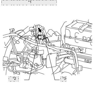
Disconnect the frame wire from the inverter with converter assembly.
*1 for LHD: *2 for RHD: -
*1 Frame Wire (HV Battery Junction Block Side) Disconnect the frame wire from the HV battery junction block.
-
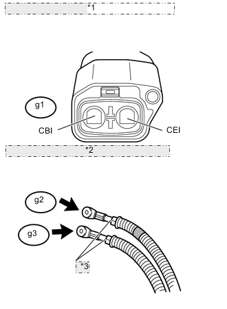
*1 Frame Wire (Inverter with Converter Assembly Side) *2 Frame Wire (HV Battery Junction Block Side) *3 Shielded Wire Ground Measure the resistance according to the value(s) in the table below.
Standard resistance Tester Connection Condition Specified Condition g2-1 - g1-1 (CBI) (Positive terminal) Power switch off Below 1 Ω g3-1 - g1-2 (CEI) (Negative terminal) Power switch off Below 1 Ω Result Result Proceed to OK A NG (for LHD) B NG (for RHD) C
B
REPLACE FRAME WIRE Click here
C
REPLACE FRAME WIRE Click here
A
-
-
CHECK HARNESS AND CONNECTOR (HYBRID VEHICLE CONTROL ECU - BATTERY PACK WIRE CONNECTORS)
-
Disconnect connectors E58 and A76 from the hybrid vehicle control ECU.
-
*1 No. 1 Battery Pack Wire Connector *2 B Side *3 A Side Disconnect the No. 1 battery pack wire connector.
Tech Tips
-
Before disconnecting the No. 1 battery pack wire connector, make sure that the connector is securely engaged.
-
Due to the time required to disconnect the HV battery junction block and hybrid vehicle converter connectors, the No. 1 battery pack wire connector resistance check should be performed before these connectors are disconnected.
-
-
Measure the resistance according to the value(s) in the table below.
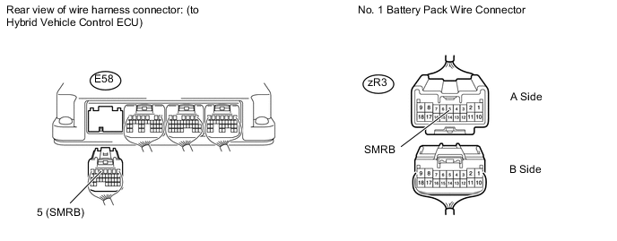
Standard resistance Tester Connection Switch Condition Specified Condition E58-5 (SMRB) - zR3-5 (SMRB) Power switch off Below 1 Ω -
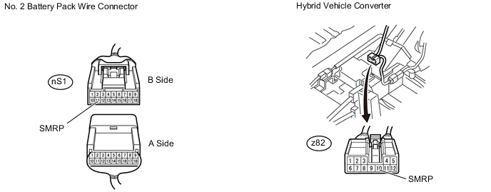
*1 No. 2 Battery Pack Wire Connector *2 A Side *3 B Side Disconnect the No. 2 battery pack wire connector.
Tech Tips
-
Before disconnecting the No. 2 battery pack wire connector, make sure that the connectors are securely engaged.
-
Due to the time required to disconnect the HV battery junction block and hybrid vehicle converter connectors, the No. 2 battery pack wire connector resistance check should be performed before these connectors are disconnected.
-
-
Measure the resistance according to the value(s) in the table below.
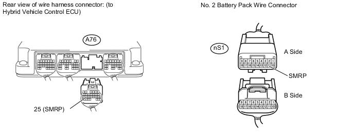
Standard resistance Tester Connection Switch Condition Specified Condition A76-25 (SMRP) - nS1-11 (SMRP) Power switch off Below 1 Ω
NG
REPAIR OR REPLACE HARNESS OR CONNECTOR
OK
-
-
CHECK CONDITION OF MAIN BATTERY CABLE CONNECTION(S)
CAUTION:
Be sure to wear insulated gloves.
-
Check that the service plug grip is not installed.
-
Check the connections between the main battery cables and the HV battery junction block.
OK The connectors are connected securely and not damaged. Tech Tips
For the removal and installation procedures related to inspection of the main battery cable connection, Click here.
-
Check for arc marks on the terminals of the main battery cable connectors.
Result Result Proceed to The terminals are connected securely and there are no contact problems. There are no arc marks. A The terminals are not connected securely and there is a contact problem. There are arc marks. B The terminals are not connected securely and there is a contact problem. There are no arc marks. C The terminals are connected securely and there are no contact problems. There are arc marks. B
B
REPLACE MALFUNCTIONING PARTS
C
CONNECT SECURELY
A
-
-
CHECK HV BATTERY ASSEMBLY
CAUTION:
Be sure to wear insulated gloves.
-
Check that the service plug grip is not installed.
-
Measure the voltage according to the value(s) in the table below.
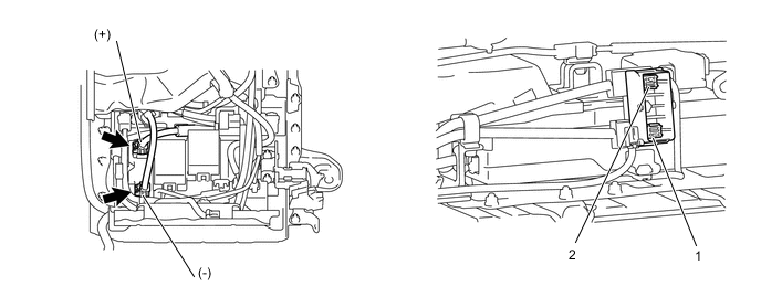
Standard voltage Tester Connection Switch Condition Specified Condition Main battery cable (+) - Service plug grip 1 Power switch off 120 V or higher Main battery cable (-) - Service plug grip 2 Power switch off 120 V or higher CAUTION:
Do not allow the probes of the electrical tester to contact each other during this inspection.
NG
REPLACE HV BATTERY Click here
OK
-
-
CHECK HARNESS AND CONNECTOR (NO. 1 BATTERY PACK WIRE CONNECTOR - HV BATTERY JUNCTION BLOCK)
CAUTION:
Be sure to wear insulated gloves.
-
Check that the service plug grip is not installed.
-
Disconnect the low voltage connector that drives the relay of the HV battery junction block.
Tech Tips
Before disconnecting the low voltage connector that drives the relay of the HV battery junction block, make sure that the connector is securely engaged.
-
Measure the resistance according to the value(s) in the table below.
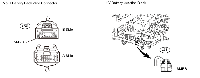
Standard resistance Tester Connection Switch Condition Specified Condition zR3-5 (SMRB) - z38-3 (SMRB) Power switch off Below 1 Ω
NG
REPAIR OR REPLACE HARNESS OR CONNECTOR
OK
-
-
CHECK HARNESS AND CONNECTOR (NO. 2 BATTERY PACK WIRE CONNECTOR - HYBRID VEHICLE CONVERTER)
CAUTION:
Be sure to wear insulated gloves.
-
Check that the service plug grip is not installed.
-
Disconnect the low voltage connector from the hybrid vehicle converter.
Tech Tips
Before disconnecting the low voltage connector of the hybrid vehicle converter, make sure that the connector is securely engaged.
-
Measure the resistance according to the value(s) in the table below.
Standard resistance Tester Connection Switch Condition Specified Condition nS1-11 (SMRP) - z82-10 (SMRP) Power switch off Below 1 Ω
NG
REPAIR OR REPLACE HARNESS OR CONNECTOR
OK
-
-
CHECK HYBRID BATTERY TERMINAL BLOCK (HV BATTERY JUNCTION BLOCK CONNECTION CONDITION)
CAUTION:
Be sure to wear insulated gloves.
-
Check that the service plug grip is not installed.
-
Check the connection between the HV battery terminal block and the HV battery junction block.
Specified Condition T= 9.0 N*m {92 kgf*cm, 80 in.*lbf} Tech Tips
For the removal and installation procedures related to inspection of the connection of the HV battery terminal block, Click here.
-
Check for arc marks on the terminals of the HV battery terminal block and HV battery junction block.
Result Result Proceed to The terminals are connected securely and there are no contact problems. There are no arc marks. A The terminals are not connected securely and there is a contact problem. There are arc marks. B The terminals are not connected securely and there is a contact problem. There are no arc marks. C The terminals are connected securely and there are no contact problems. There are arc marks. B
B
REPLACE MALFUNCTIONING PARTS
C
CONNECT SECURELY
A
-
-
CHECK HYBRID BATTERY TERMINAL BLOCK
CAUTION:
Be sure to wear insulated gloves.
-
Check that the service plug grip is not installed.
-
Remove the HV battery terminal block from the HV battery pack.
-
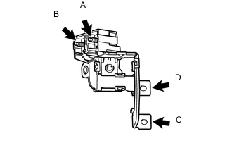
Measure the resistance according to the value(s) in the table below.
Standard resistance Tester Connection Switch Condition Specified Condition A - C Power switch off Below 1 Ω B - D Power switch off Below 1 Ω
NG
REPLACE HYBRID BATTERY TERMINAL BLOCK Click here
OK
-
-
INSPECT HV BATTERY JUNCTION BLOCK (SMRB)
CAUTION:
Be sure to wear insulated gloves.
-
Check that the service plug grip is not installed.
-
Remove the HV battery junction block from the vehicle Click here.
-
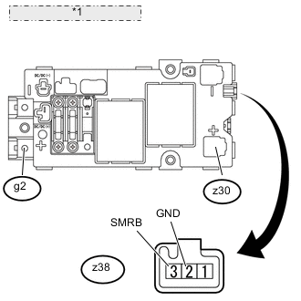
*1 HV Battery Junction Block Measure the resistance according to the value(s) in the table below.
Standard resistance Tester Connection Condition Specified Condition g2-1 - z30-1 Auxiliary battery voltage is applied between terminals z38-3 (SMRB) and z38-2 (GND). Below 1 Ω -
Measure the resistance according to the value(s) in the table below.
Standard resistance Tester Connection Condition Specified Condition z38-3 (SMRB) - z38-2 (GND) -35 to 80°C
(-31 to 176° F)
18.8 to 32.1 Ω
NG
REPLACE HV BATTERY JUNCTION BLOCK Click here
OK
-
-
CHECK FOR INTERMITTENT PROBLEMS
-
Check for intermittent problems Click here.
Tech Tips
If DTC P3004-131 is output again after performing the inspection, replace the hybrid vehicle converter. If DTC P3004-131 is not output again, replace the HV battery junction block.
OK
REPLACE HV BATTERY JUNCTION BLOCK Click here
NG
REPLACE HYBRID VEHICLE CONVERTER Click here
-