HYBRID CONTROL SYSTEM, Diagnostic DTC:P0C2E-859
| DTC Code | DTC Name |
|---|---|
| P0C2E-859 | Auxiliary Transmission Fluid Pump Control Module Feedback Signal High |
DESCRIPTION
Refer to the description for DTC P0C29-865 Click here.
| DTC No. | INF Code | DTC Detection Condition | Trouble Area |
|---|---|---|---|
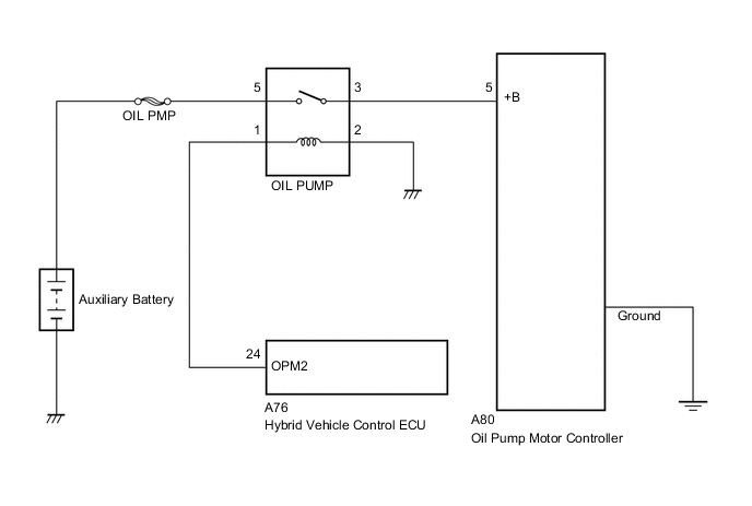
| P0C2E | 859 | Open or short to +B in the OPST (status signal line) circuit |
|
CAUTION / NOTICE / HINT
Note
If P0C2D-858 is also output, troubleshoot P0C2D-858 first.
PROCEDURE
-
CHECK HYBRID VEHICLE CONTROL ECU (CHECK WAVEFORM)
-
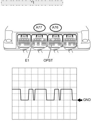
*1 Component with harness connected: (Hybrid Vehicle Control ECU) Connect an oscilloscope between the hybrid vehicle control ECU terminals specified in the table below, and measure the waveform.
Item Contents Terminal A76-33 (OPST) - A77-7 (E1) Equipment Setting 5 V/DIV., 5 ms./DIV. Condition Power switch on (IG) Result Result Proceed to Waveform is flat, and is stuck on the +B side. A Normal B
B 
CHECK FOR INTERMITTENT PROBLEMS Click here
A 
-
-
CHECK CONNECTOR CONNECTION CONDITION (OIL PUMP MOTOR CONTROLLER CONNECTOR)
Note
Before disconnecting the connectors, confirm that they are properly connected by checking that the locking claws are engaged and that the connectors do not pull out.
-
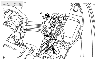
*1 Oil Pump Motor Controller Check the connections of the oil pump motor controller connectors.
OK The connectors are connected securely and there are no contact problems. Tech Tips
For connector A, when connecting it, insert it with the locking lever in the raised position. Rotate the lever downward and make sure that the connector is pulled into its socket. When the locking lever is in its fully closed position, a click will be heard as its locking claws engage. After the click is heard, pull up on the connector to confirm that it is properly connected.
NG 
CONNECT SECURELY
OK
-
-
CHECK CONNECTOR CONNECTION CONDITION (HYBRID VEHICLE CONTROL ECU CONNECTOR)
-
*1 Hybrid Vehicle Control ECU Check the connections of the hybrid vehicle control ECU connectors.
OK The connectors are connected securely and there are no contact problems.
NG
CONNECT SECURELY
OK
-
-
CHECK OIL PUMP MOTOR CONTROLLER
-
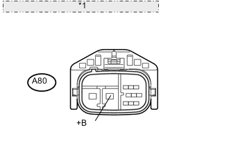
*1 Front view of wire harness connector: (to Oil Pump Motor Controller) Turn the power switch off.
-
Disconnect connector A80 from the oil pump motor controller.
-
Turn the power switch on (IG).
-
Measure the voltage according to the value(s) in the table below.
Standard voltage Tester Connection Switch Condition Specified Condition A80-5 (+B) - Body ground Power switch on (IG) 11 to 14 V Note
Turning the power switch on (IG) with the oil pump motor controller connector disconnected causes other DTCs to be stored. Clear the DTCs after performing this inspection.
NG
CHECK FUSIBLE LINK BLOCK ASSEMBLY (OIL PMP) Click here
OK
-
-
CHECK HARNESS AND CONNECTOR (HYBRID VEHICLE CONTROL ECU - OIL PUMP MOTOR CONTROLLER)
-
Turn the power switch off.
-
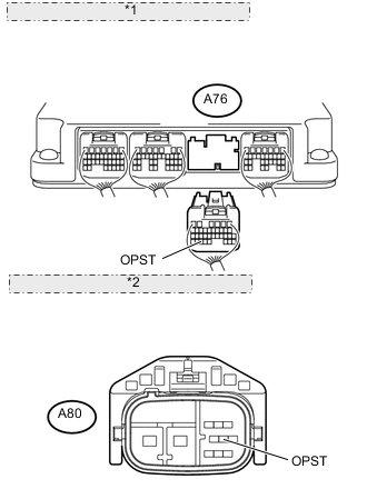
*1 Rear view of wire harness connector: (to Hybrid Vehicle Control ECU) *2 Front view of wire harness connector: (to Oil Pump Motor Controller) Disconnect connector A76 from the hybrid vehicle control ECU.
-
Disconnect connector A80 from the oil pump motor controller.
-
Turn the power switch on (IG).
-
Measure the voltage according to the value(s) in the table below.
Standard voltage Tester Connection Switch Condition Specified Condition A76-33 (OPST) - Body ground Power switch on (IG) Below 1 V Note
Turning the power switch on (IG) with the hybrid vehicle control ECU and oil pump motor controller connectors disconnected causes other DTCs to be stored. Clear the DTCs after performing this inspection.
-
Turn the power switch off.
-
Measure the resistance according to the value(s) in the table below.
Standard resistance (Check for open) Tester Connection Switch Condition Specified Condition A76-33 (OPST) - A80-7 (OPST) Power switch off Below 1 Ω Standard resistance (Check for short) Tester Connection Switch Condition Specified Condition A76-33 (OPST) or A80-7 (OPST) - Body ground and other terminals Power switch off 10 kΩ or higher
NG
REPAIR OR REPLACE HARNESS OR CONNECTOR
OK
-
-
CHECK HYBRID VEHICLE CONTROL ECU
-
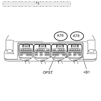
*1 Component with harness connected: (Hybrid Vehicle Control ECU) Turn the power switch off.
-
Measure the resistance according to the value(s) in the table below.
Standard resistance Tester Connection Switch Condition Specified Condition A76-33 (OPST) - A78-1 (+B1) Power switch off 6.5 to 8.5 Ω
NG
REPLACE HYBRID VEHICLE CONTROL ECU Click here
OK
-
-
CHECK IF PART IS CORRECTLY GROUNDED
-
Measure the resistance according to the value(s) in the table below.
Standard resistance Tester Connection Switch Condition Specified Condition Oil pump motor controller - Body ground Power switch off Below 1 Ω
OK
REPLACE OIL PUMP MOTOR CONTROLLER Click here
NG
REPAIR OR REPLACE OIL PUMP MOTOR CONTROLLER
-
-
CHECK FUSIBLE LINK BLOCK ASSEMBLY (OIL PMP)
-
Check if there is an open circuit in the fusible link (OIL PMP) in the engine room No. 1 junction block.
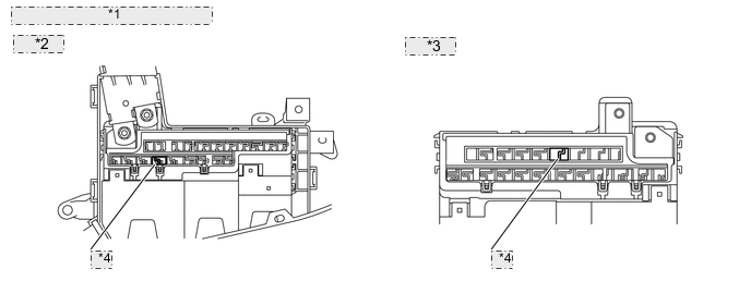
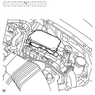
*1 Engine Room No. 1 Junction Block *2 for LHD: *3 for RHD: *4 OIL PMP OK There is no open circuit in the fusible link (OIL PMP).
NG
REPLACE FUSIBLE LINK BLOCK ASSEMBLY
OK
-
-
CHECK HARNESS AND CONNECTOR
-
Turn the power switch off.
-
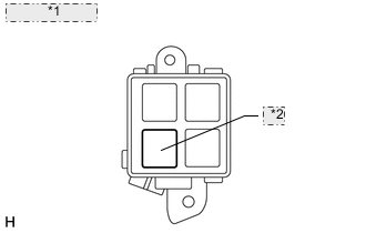
*1 Engine Room No. 5 Relay Block *2 OIL PMP Relay Remove the OIL PMP relay from the engine room No. 5 relay block.
-
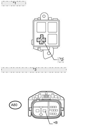
*1 Engine Room No. 5 Relay Block *2 OIL PMP Relay *3 Front view of wire harness connector: (to Oil Pump Motor Controller) Measure the resistance according to the value(s) in the table below.
Standard resistance (Check for open) Tester Connection Switch Condition Specified Condition Engine room No. 5 relay block OIL PMP relay terminal 3 - A80-5 (+B) Power switch off Below 1 Ω Engine room No. 5 relay block OIL PMP relay terminal 2 - Body ground Power switch off Below 1 Ω Standard resistance (Check for short) Tester Connection Switch Condition Specified Condition Engine room No. 5 relay block OIL PMP relay terminal 3 - Body ground Power switch off 10 kΩ or higher
NG
REPAIR OR REPLACE HARNESS OR CONNECTOR
OK
-
-
CHECK RELAY (OIL PMP)
-
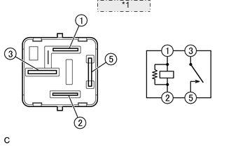
*1 OIL PMP Relay Measure the resistance according to the value(s) in the table below.
Standard resistance Tester Connection Condition Specified Condition 1 - 2 Always 151 to 203 Ω 3 - 5 Auxiliary battery voltage is not applied between terminals 1 and 2. 10 kΩ or higher Auxiliary battery voltage is applied between terminals 1 and 2. Below 1 Ω
NG
REPLACE RELAY (OIL PMP) Click here
OK
-
-
CHECK HARNESS AND CONNECTOR
-
Turn the power switch off.
-
*1 Engine Room No. 5 Relay Block *2 OIL PMP Relay Measure the voltage according to the value(s) in the table below.
Standard voltage Tester Connection Switch Condition Specified Condition Engine room No. 5 relay block OIL PMP relay terminal 5 - Body ground Power switch off 11 to 14 V
NG
REPAIR OR REPLACE HARNESS OR CONNECTOR
OK
-
-
CHECK HYBRID VEHICLE CONTROL ECU
-
Turn the power switch on (IG).
-
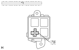
*1 Engine Room No. 5 Relay Block *2 OIL PMP Relay Measure the voltage according to the value(s) in the table below.
Standard voltage Tester Connection Switch Condition Specified Condition Engine room No. 5 relay block OIL PMP relay terminal 1 - Body ground Power switch on (IG) 11 to 14 V
OK
REPLACE HYBRID VEHICLE CONTROL ECU Click here
NG
-
-
CHECK HARNESS AND CONNECTOR (HYBRID VEHICLE CONTROL ECU - ENGINE ROOM NO. 5 RELAY BLOCK)
-
Turn the power switch off.
-
Disconnect connector A76 from the hybrid vehicle control ECU.
-
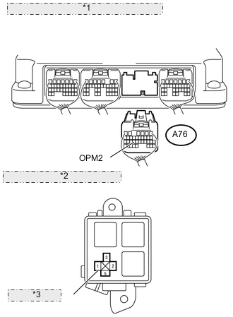
*1 Rear view of wire harness connector: (to Hybrid Vehicle Control ECU) *2 Engine Room No. 5 Relay Block *3 OIL PMP Relay Measure the resistance according to the value(s) in the table below.
Standard resistance (Check for open) Tester Connection Switch Condition Specified Condition A76-24 (OPM2) - Engine room No. 5 relay block OIL PMP relay terminal 1 Power switch off Below 1 Ω Standard resistance (Check for short) Tester Connection Switch Condition Specified Condition A76-24 (OPM2) or Engine room No. 5 relay block OIL PMP relay terminal 1 - Body ground Power switch off 10 kΩ or higher
OK
REPLACE HYBRID VEHICLE CONTROL ECU Click here
NG
REPAIR OR REPLACE HARNESS OR CONNECTOR
-
-
CHECK FOR INTERMITTENT PROBLEMS
-
Check for intermittent problems Click here.
OK
REPLACE HYBRID VEHICLE CONTROL ECU Click here
NG
REPAIR OR REPLACE MALFUNCTIONING PARTS, COMPONENT AND AREA
-