HYBRID CONTROL SYSTEM, Diagnostic DTC:P0AA6-526, P0AA6-611, P0AA6-612, P0AA6-613, P0AA6-614
| DTC Code | DTC Name |
|---|---|
| P0AA6-526 | Hybrid Battery Voltage System Isolation Fault |
| P0AA6-611 | Hybrid Battery Voltage System Isolation Fault |
| P0AA6-612 | Hybrid Battery Voltage System Isolation Fault |
| P0AA6-613 | Hybrid Battery Voltage System Isolation Fault |
| P0AA6-614 | Hybrid Battery Voltage System Isolation Fault |
DESCRIPTION
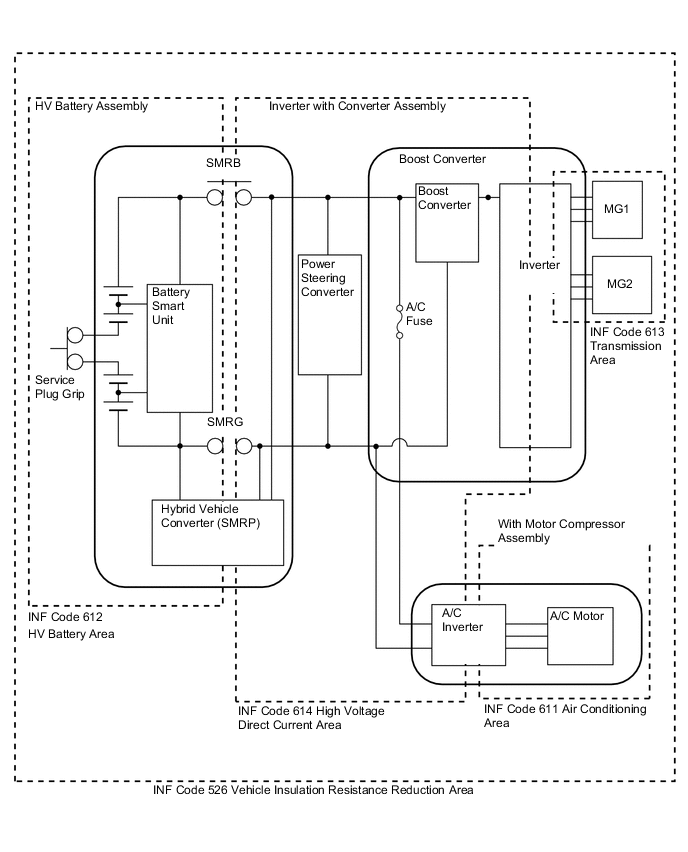
The hybrid vehicle control ECU monitors the battery smart unit and detects insulation malfunctions in the high-voltage system.
| DTC No. | INF Code | DTC Detection Condition | Trouble Area |
|---|---|---|---|
| P0AA6 | 526 (*1) | Insulation resistance between the high-voltage circuit and the body has decreased. |
|
| P0AA6 | 611 | Insulation resistance of the with motor compressor assembly has decreased. | With motor compressor assembly |
| P0AA6 | 612 | Insulation resistance of the HV battery area has decreased. |
|
| P0AA6 | 613 | Insulation resistance of the transmission area has decreased. |
|
| P0AA6 | 614 | Insulation resistance of the high-voltage DC area has decreased. |
|
Tech Tips
-
*1: INF code 526 is stored together with P0AA6.
-
If P0AA6 is stored, the hybrid system cannot be turned on until the DTC is cleared using the intelligent tester.
-
If P0AA6 is stored while driving, the vehicle can drive for the remainder of that trip.
-
When measuring insulation resistance using a megohmmeter, measure the resistance while jiggling the high-voltage wire harness.
WIRING DIAGRAM
CAUTION / NOTICE / HINT
CAUTION:
-
When troubleshooting P0AA6, be sure to wrap tools with electrical tape. (It is very dangerous if high voltage is shorted to ground through tools.)
-
Before inspecting the high-voltage system or disconnecting the low voltage connector of the inverter with converter assembly, take safety precautions such as wearing insulated gloves and removing the service plug grip to prevent electrical shocks. After removing the service plug grip, put it in your pocket to prevent other technicians from accidentally reconnecting it while you are working on the high-voltage system.
-
After disconnecting the service plug grip, wait for at least 10 minutes before touching any of the high-voltage connectors or terminals. After waiting for 10 minutes, check the voltage at the terminals in the inspection point in the inverter with converter assembly. The voltage should be 0 V before beginning work.
Tech Tips
-
Waiting for at least 10 minutes is required to discharge the high-voltage capacitor inside the inverter with converter assembly.
-
When measuring insulation resistance using a megohmmeter, set the megohmmeter to 500 V.
PROCEDURE
-
CHECK DTC OUTPUT (HV)
-
Connect the intelligent tester to the DLC3.
-
Turn the power switch on (IG).
-
Select the following menu items: Powertrain / Hybrid Control / Trouble Codes.
-
Check if DTCs are output.
Result Result Proceed to P0AA6 only is output. A P0AA6 and P0A1D (hybrid vehicle control ECU malfunction) are output. B P0AA6 and P0AA7 (malfunction in the battery smart unit) are output. C P0AA6 and P0AFC (battery ECU malfunction) are output. D
B 
GO TO INSPECTION PROCEDURE RELEVANT TO OUTPUT DTC (P0A1D) Click here
C
GO TO INSPECTION PROCEDURE RELEVANT TO OUTPUT DTC (P0AA7) Click here
D
GO TO INSPECTION PROCEDURE RELEVANT TO OUTPUT DTC (P0AFC) Click here
A 
-
-
CHECK INFORMATION CODE
-
Select the following menu items: Powertrain / Hybrid Control / Trouble Codes.
-
Access the freeze frame data of DTC P0AA6 and read the INF code.
Note
INF codes 611, 612, 613, and 614 are not stored at the same time with INF code 526. If only INF code 526 is output, turn the power switch off and wait 30 seconds to determine the malfunctioning area. Then, turn the power switch on (IG) and read the INF code again.
Result Result Proceed to 526 (decrease in the insulation resistance of the high-voltage circuit) only is output. A 526 and 611 (decrease in the insulation resistance of the air conditioner area) are output. B 526 and 612 (decrease in the insulation resistance of the HV battery area) are output. C 526 and 613 (decrease in the insulation resistance of the transmission area) are output. D 526 and 614 (decrease in the insulation resistance of the high-voltage DC area) are output. E
B
GO TO AIR CONDITIONING SYSTEM (P0AA6-611) Click here
C 
CHECK HV BATTERY AREA Click here
D
CHECK INVERTER WITH CONVERTER ASSEMBLY Click here
E
CHECK MOTOR CABLE Click here
A
-
-
CHECK AIR CONDITIONING HARNESS ASSEMBLY (CONNECTION CONDITION)
CAUTION:
Be sure to wear insulated gloves.
-
Turn the power switch off.
-
Remove the service plug grip. Click here
Note
After removing the service plug grip, do not turn the power switch on (READY) unless instructed by the repair manual because this may cause a malfunction.
-
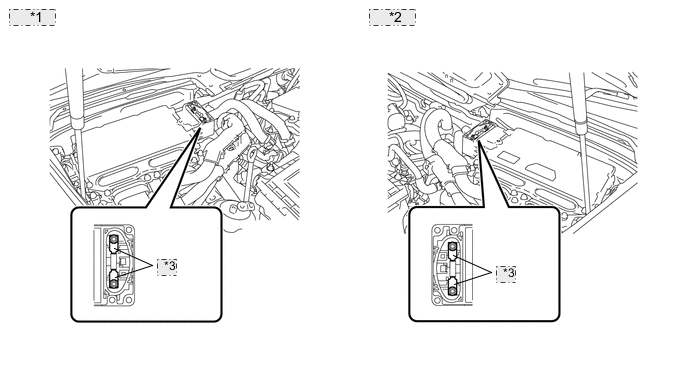
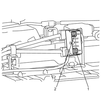
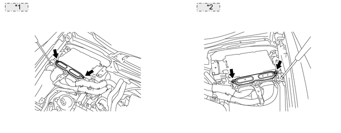
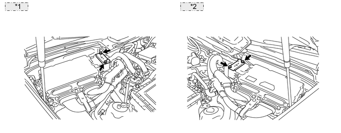
Check the condition of the air conditioning harness assembly connector.
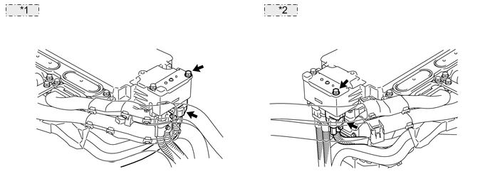
*1 for LHD: *2 for RHD: OK The connector is connected securely and there are no contact problems. -
Check for arc marks on the terminals of the air conditioning harness assembly.
Result Result Proceed to The terminals are connected securely and there are no contact problems. There are no arc marks. A The terminals are not connected securely and there is a contact problem. There are arc marks. B The terminals are not connected securely and there is a contact problem. There are no arc marks. C The terminals are connected securely and there are no contact problems. There are arc marks. B
B
REPLACE MALFUNCTIONING PARTS
C
CONNECT SECURELY
A
-
-
CHECK AIR CONDITIONING HARNESS ASSEMBLY
CAUTION:
Be sure to wear insulated gloves.
-
Check that the service plug grip is not installed.
-
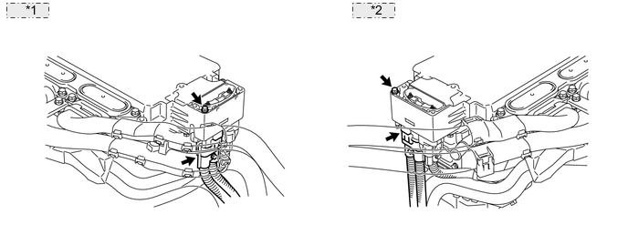
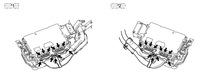
Disconnect the air conditioning harness assembly from the inverter with converter assembly.
*1 for LHD: *2 for RHD: -
Make sure that no foreign objects have entered or contaminated the connector of the air conditioning harness assembly.
-
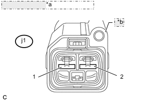
*a Air Conditioning Harness Assembly *b Shielded Wire Ground Using a megohmmeter set to 500 V, measure the resistance according to the value(s) in the table below.
Note
Be sure to set the megohmmeter to 500 V when performing this test. Using a setting higher than 500 V can result in damage to the component being inspected.
Standard resistance Tester Connection Switch Condition Specified Condition j1-1 (ACPE) - Body ground and shielded wire ground Power switch off 3 MΩ or higher j1-2 (ACPB) - Body ground and shielded wire ground Power switch off 3 MΩ or higher
NG
CHECK AIR CONDITIONING HARNESS ASSEMBLY Click here
OK
-
-
CHECK CONDITION OF FRAME WIRE CONNECTION(S)
CAUTION:
Be sure to wear insulated gloves.
-
Check that the service plug grip is not installed.
-
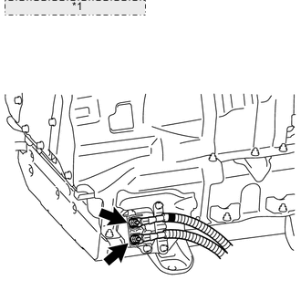
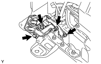
Check the connection between the frame wire and the inverter with converter assembly.
*1 for LHD: *2 for RHD: OK The connector is connected securely and there are no contact problems. Tech Tips
Make sure that no foreign objects have entered or contaminated the inverter with converter assembly.
NG
CONNECT SECURELY
OK
-
-
CHECK INVERTER WITH CONVERTER ASSEMBLY
CAUTION:
Be sure to wear insulated gloves.
-
Check that the service plug grip is not installed.
-
Disconnect the frame wire from the inverter with converter assembly.
Tech Tips
Make sure that no foreign objects have entered or contaminated the connector of the frame wire.
*1 for LHD: *2 for RHD: -
Using a megohmmeter set to 500 V, measure the resistance according to the value(s) in the table below.
*1 for LHD: *2 for RHD: *3 A/C Fuse Note
Be sure to set the megohmmeter to 500 V when performing this test. Using a setting higher than 500 V can result in damage to the component being inspected.
Standard resistance Tester Connection Switch Condition Specified Condition A/C fuse - Body ground Power switch off 1.0 MΩ or higher Tech Tips
Perform this inspection with the air conditioning harness assembly disconnected from the inverter with converter assembly.
NG
CHECK MOTOR CABLE Click here
OK
-
-
CHECK FRAME WIRE
CAUTION:
Be sure to wear insulated gloves.
-
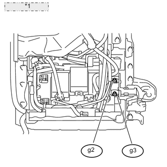
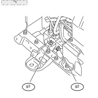
*1 Frame Wire (HV Battery Junction Block Side) Check that the service plug grip is not installed.
-
Disconnect the frame wire from the HV battery junction block.
Tech Tips
For the removal and installation procedures related to the frame wire, (See page for LHD, Click here for RHD).
-
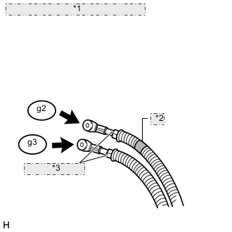
*1 Frame Wire (HV Battery Junction Block Side) *2 Red Mark *3 Shielded Wire Ground Using a megohmmeter set to 500 V, measure the resistance according to the value(s) in the table below.
Note
Be sure to set the megohmmeter to 500 V when performing this test. Using a setting higher than 500 V can result in damage to the component being inspected.
Standard resistance Tester Connection Switch Condition Specified Condition g2-1 - Body ground and shielded wire ground Power switch off 10 MΩ or higher g3-1 - Body ground and shielded wire ground Power switch off 10 MΩ or higher Result Result Proceed to OK A NG (for LHD) B NG (for RHD) C
B
REPLACE FRAME WIRE Click here
C
REPLACE FRAME WIRE Click here
A
-
-
CHECK HV BATTERY JUNCTION BLOCK
CAUTION:
Be sure to wear insulated gloves.
-
Check that the service plug grip is not installed.
-
Disconnect the high-voltage connectors of the HV battery from the HV battery junction block.
-
*1 Battery Carrier Using a megohmmeter set to 500 V, measure the resistance according to the value(s) in the table below.
Note
Be sure to set the megohmmeter to 500 V when performing this test. Using a setting higher than 500 V can result in damage to the component being inspected.
Standard resistance Tester Connection Switch Condition Specified Condition g3-1 - Battery carrier Power switch off 10 MΩ or higher g2-1 - Battery carrier Power switch off 10 MΩ or higher
NG
CHECK POWER STEERING CONVERTER Click here
OK
-
-
CHECK HV BATTERY AREA
CAUTION:
Be sure to wear insulated gloves.
-
Turn the power switch off.
-
Remove the service plug grip. Click here
Note
After removing the service plug grip, do not turn the power switch on (READY) unless instructed by the repair manual because this may cause a malfunction.
-
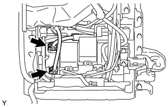
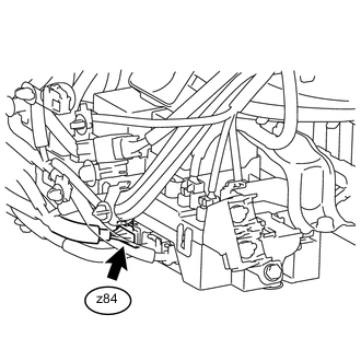
Disconnect the orange-colored connector z32 from the battery smart unit.
Tech Tips
For the removal and installation procedures related to the battery smart unit connector, Click here.
-
Using a megohmmeter set to 500 V, measure the resistance according to the value(s) in the table below.
Note
Be sure to set the megohmmeter to 500 V when performing this test. Using a setting higher than 500 V can result in damage to the component being inspected.
Standard resistance Tester Connection Switch Condition Specified Condition Service plug grip 1 - Body ground Power switch off 10 MΩ or higher Service plug grip 2 - Body ground Power switch off 10 MΩ or higher Note
Perform this inspection with the high-voltage connectors of the hybrid vehicle converter connected.
OK
REPLACE BATTERY SMART UNIT Click here
NG
-
-
CHECK HV CONVERTER
CAUTION:
Be sure to wear insulated gloves.
-
Check that the service plug grip is not installed.
-
*1 Hybrid Vehicle Converter Disconnect the hybrid vehicle converter connectors from the HV battery junction block.
Tech Tips
For the removal and installation procedures related to the hybrid vehicle converter connectors, Click here.
-
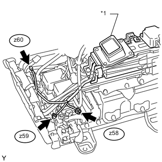
*1 Hybrid Vehicle Converter Using a megohmmeter set to 500 V, measure the resistance according to the value(s) in the table below.
Note
Be sure to set the megohmmeter to 500 V when performing this test. Using a setting higher than 500 V can result in damage to the component being inspected.
Standard resistance Tester Connection Switch Condition Specified Condition z60-1 (INR) - Hybrid vehicle converter Power switch off 10 MΩ or higher z58-1 (CBD) - Hybrid vehicle converter Power switch off 10 MΩ or higher z59-1 (CED) - Hybrid vehicle converter Power switch off 10 MΩ or higher
NG
REPLACE HV CONVERTER Click here
OK
-
-
CHECK HV BATTERY JUNCTION BLOCK
CAUTION:
Be sure to wear insulated gloves.
-
Check that the service plug grip is not installed.
-
Disconnect the high-voltage connectors of the HV battery from the HV battery junction block.
-
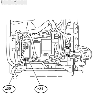
*1 Battery Carrier Using a megohmmeter set to 500 V, measure the resistance according to the value(s) in the table below.
Note
Be sure to set the megohmmeter to 500 V when performing this test. Using a setting higher than 500 V can result in damage to the component being inspected.
Standard resistance Tester Connection Switch Condition Specified Condition z30-1 - Battery carrier Power switch off 10 MΩ or higher z34-1 - Battery carrier Power switch off 10 MΩ or higher
OK
REPLACE HV BATTERY Click here
NG
REPLACE HV BATTERY JUNCTION BLOCK Click here
-
-
CHECK MOTOR CABLE
CAUTION:
Be sure to wear insulated gloves.
-
Turn the power switch off.
-
Remove the service plug grip. Click here
Note
After removing the service plug grip, do not turn the power switch on (READY) unless instructed by the repair manual because this may cause a malfunction.
-
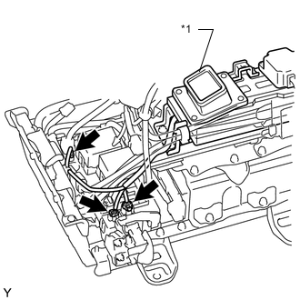
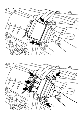
Remove the inverter terminal cover from the inverter with converter assembly.
-
For LHD vehicles, use the following procedures Click here.
-
For RHD vehicles, use the following procedures Click here.
Note
Lift the inverter terminal cover horizontally so that it does not tilt. Failure to do so may break the inverter cover guide pins.
*1 for LHD: *2 for RHD: -
-
Disconnect the motor cable and generator cable from the inverter with converter assembly.
*1 for LHD: *2 for RHD: -
Using a megohmmeter set to 500 V, measure the resistance according to the value(s) in the table below.
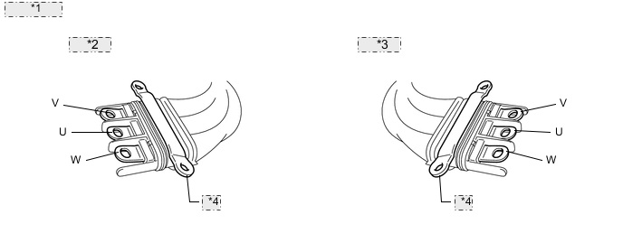
*1 Motor Cable *2 for LHD: *3 for RHD: *4 Shielded Wire Ground Note
Be sure to set the megohmmeter to 500 V when performing this test. Using a setting higher than 500 V can result in damage to the component being inspected.
Standard resistance Tester Connection Switch Condition Specified Condition U - Body ground and shielded wire ground Power switch off 100 MΩ or higher V - Body ground and shielded wire ground Power switch off 100 MΩ or higher W - Body ground and shielded wire ground Power switch off 100 MΩ or higher
NG
CHECK MOTOR CABLE Click here
OK
-
-
CHECK GENERATOR CABLE
CAUTION:
Be sure to wear insulated gloves.
-
Check that the service plug grip is not installed.
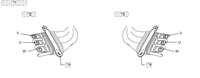
*1 Generator Cable *2 for LHD: *3 for RHD: *4 Shielded Wire Ground -
Using a megohmmeter set to 500 V, measure the resistance according to the value(s) in the table below.
Note
Be sure to set the megohmmeter to 500 V when performing this test. Using a setting higher than 500 V can result in damage to the component being inspected.
Standard resistance Tester Connection Switch Condition Specified Condition U - Body ground and shielded wire ground Power switch off 100 MΩ or higher V - Body ground and shielded wire ground Power switch off 100 MΩ or higher W - Body ground and shielded wire ground Power switch off 100 MΩ or higher Result Result Proceed to OK (for LHD) A OK (for RHD) B NG C
A
REPLACE INVERTER WITH CONVERTER ASSEMBLY Click here
B
REPLACE INVERTER WITH CONVERTER ASSEMBLY Click here
C
CHECK GENERATOR CABLE Click here
-
-
CHECK AIR CONDITIONING HARNESS ASSEMBLY
CAUTION:
Be sure to wear insulated gloves.
-
Turn the power switch off.
-
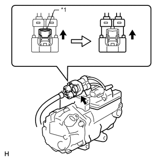
*1 Green Lock Remove the service plug grip. Click here
Note
After removing the service plug grip, do not turn the power switch on (READY) unless instructed by the repair manual because this may cause a malfunction.
-
Disconnect the air conditioning harness assembly from the with motor compressor assembly.
-
*a Air Conditioning Harness Assembly *b Shielded Wire Ground Using a megohmmeter set to 500 V, measure the resistance according to the value(s) in the table below.
Note
Be sure to set the megohmmeter to 500 V when performing this test. Using a setting higher than 500 V can result in damage to the component being inspected.
Standard resistance Tester Connection Switch Condition Specified Condition j1-1 (ACPE) - Body ground and shielded wire ground Power switch off 10 MΩ or higher j1-2 (ACPB) - Body ground and shielded wire ground Power switch off 10 MΩ or higher
OK
GO TO AIR CONDITIONING SYSTEM (P0AA6-611) Click here
NG
REPLACE AIR CONDITIONING HARNESS ASSEMBLY
-
-
CHECK MOTOR CABLE
CAUTION:
Be sure to wear insulated gloves.
-
Turn the power switch off.
-
Remove the service plug grip. Click here
Note
After removing the service plug grip, do not turn the power switch on (READY) unless instructed by the repair manual because this may cause a malfunction.
-
Remove the inverter terminal cover from the inverter with converter assembly.
-
For LHD vehicles, use the following procedures Click here.
-
For RHD vehicles, use the following procedures Click here.
Note
Lift the inverter terminal cover horizontally so that it does not tilt. Failure to do so may break the inverter cover guide pins.
*1 for LHD: *2 for RHD: -
-
Disconnect the motor cable and generator cable from the inverter with converter assembly.
*1 for LHD: *2 for RHD: -
Using a megohmmeter set to 500 V, measure the resistance according to the value(s) in the table below.
*1 Motor Cable *2 for LHD: *3 for RHD: *4 Shielded Wire Ground Note
Be sure to set the megohmmeter to 500 V when performing this test. Using a setting higher than 500 V can result in damage to the component being inspected.
Standard resistance Tester Connection Switch Condition Specified Condition U - Body ground and shielded wire ground Power switch off 100 MΩ or higher V - Body ground and shielded wire ground Power switch off 100 MΩ or higher W - Body ground and shielded wire ground Power switch off 100 MΩ or higher
NG
CHECK MOTOR CABLE Click here
OK
-
-
CHECK GENERATOR CABLE
CAUTION:
Be sure to wear insulated gloves.
-
Check that the service plug grip is not installed.
*1 Generator Cable *2 for LHD: *3 for RHD: *4 Shielded Wire Ground -
Using a megohmmeter set to 500 V, measure the resistance according to the value(s) in the table below.
Note
Be sure to set the megohmmeter to 500 V when performing this test. Using a setting higher than 500 V can result in damage to the component being inspected.
Standard resistance Tester Connection Switch Condition Specified Condition U - Body ground and shielded wire ground Power switch off 100 MΩ or higher V - Body ground and shielded wire ground Power switch off 100 MΩ or higher W - Body ground and shielded wire ground Power switch off 100 MΩ or higher
NG
CHECK GENERATOR CABLE Click here
OK
-
-
CHECK HIGH-VOLTAGE DIRECT CURRENT AREA
CAUTION:
Be sure to wear insulated gloves.
-
Turn the power switch off.
-
Remove the service plug grip Click here.
Note
After removing the service plug grip, do not turn the power switch on (READY) unless instructed by the repair manual because this may cause a malfunction.
-
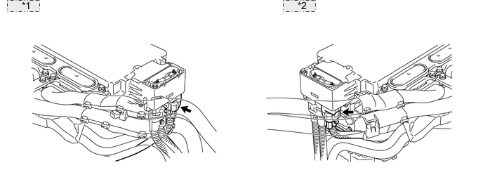
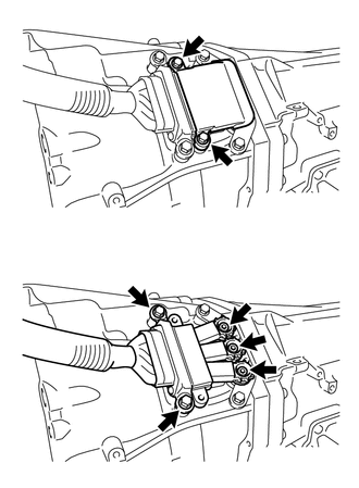
Remove the connector cover from the inverter with converter assembly.
*1 for LHD: *2 for RHD: -
Disconnect the frame wire from the inverter with converter assembly.
*1 for LHD: *2 for RHD: -
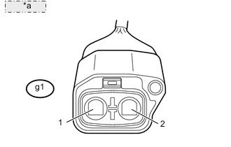
*a Frame Wire Using a megohmmeter set to 500 V, measure the resistance according to the value(s) in the table below.
Note
Be sure to set the megohmmeter to 500 V when performing this test. Using a setting higher than 500 V can result in damage to the component being inspected.
Standard resistance Tester Connection Switch Condition Specified Condition g1-1 (CBI) - Body ground Power switch off 10 MΩ or higher g1-2 (CEI) - Body ground Power switch off 10 MΩ or higher
NG
CHECK FRAME WIRE Click here
OK
-
-
CHECK AIR CONDITIONING HARNESS ASSEMBLY
CAUTION:
Be sure to wear insulated gloves.
-
Check that the service plug grip is not installed.
-
Disconnect the air conditioning harness assembly from the inverter with converter assembly.
*1 for LHD: *2 for RHD: -
*a Air Conditioning Harness Assembly *b Shielded Wire Ground Using a megohmmeter set to 500 V, measure the resistance according to the value(s) in the table below.
Note
Be sure to set the megohmmeter to 500 V when performing this test. Using a setting higher than 500 V can result in damage to the component being inspected.
Standard resistance Tester Connection Switch Condition Specified Condition j1-1 (ACPE) - Body ground and shielded wire ground Power switch off 3 MΩ or higher j1-2 (ACPB) - Body ground and shielded wire ground Power switch off 3 MΩ or higher Result Result Proceed to OK (for LHD) A OK (for RHD) B NG C
A
REPLACE INVERTER WITH CONVERTER ASSEMBLY Click here
B
REPLACE INVERTER WITH CONVERTER ASSEMBLY Click here
C
-
-
CHECK AIR CONDITIONING HARNESS ASSEMBLY
CAUTION:
Be sure to wear insulated gloves.
-
*1 Green Lock Check that the service plug grip is not installed.
-
Disconnect the air conditioning harness assembly from the with motor compressor assembly.
-
*a Air Conditioning Harness Assembly *b Shielded Wire Ground Using a megohmmeter set to 500 V, measure the resistance according to the value(s) in the table below.
Note
Be sure to set the megohmmeter to 500 V when performing this test. Using a setting higher than 500 V can result in damage to the component being inspected.
Standard resistance Tester Connection Switch Condition Specified Condition j1-1 (ACPE) - Body ground and shielded wire ground Power switch off 10 MΩ or higher j1-2 (ACPB) - Body ground and shielded wire ground Power switch off 10 MΩ or higher
OK
GO TO AIR CONDITIONING SYSTEM (P0AA6-611) Click here
NG
REPLACE AIR CONDITIONING HARNESS ASSEMBLY
-
-
CHECK FRAME WIRE
CAUTION:
Be sure to wear insulated gloves.
-
*1 Frame Wire (HV Battery Junction Block Side) Check that the service plug grip is not installed.
-
Disconnect the frame wire from the HV battery junction block.
Tech Tips
For the removal and installation procedures related to the frame wire, (See page for LHD, Click here for RHD).
-
*1 Frame Wire (HV Battery Junction Block Side) *2 Red Mark *3 Shielded Wire Ground Using a megohmmeter set to 500 V, measure the resistance according to the value(s) in the table below.
Note
Be sure to set the megohmmeter to 500 V when performing this test. Using a setting higher than 500 V can result in damage to the component being inspected.
Standard resistance Tester Connection Switch Condition Specified Condition g2-1 - Body ground and shielded wire ground Power switch off 10 MΩ or higher g3-1 - Body ground and shielded wire ground Power switch off 10 MΩ or higher Result Result Proceed to OK A NG (for LHD) B NG (for RHD) C
B
REPLACE FRAME WIRE Click here
C
REPLACE FRAME WIRE Click here
A
-
-
CHECK HV CONVERTER
CAUTION:
Be sure to wear insulated gloves.
-
Check that the service plug grip is not installed.
-
*1 Hybrid Vehicle Converter Disconnect the hybrid vehicle converter connectors from the HV battery junction block.
Tech Tips
For the removal and installation procedures related to the hybrid vehicle converter connectors, Click here.
-
*1 Hybrid Vehicle Converter Using a megohmmeter set to 500 V, measure the resistance according to the value(s) in the table below.
Note
Be sure to set the megohmmeter to 500 V when performing this test. Using a setting higher than 500 V can result in damage to the component being inspected.
Standard resistance Tester Connection Switch Condition Specified Condition z60-1 (INR) - Hybrid vehicle converter Power switch off 10 MΩ or higher z58-1 (CBD) - Hybrid vehicle converter Power switch off 10 MΩ or higher z59-1 (CED) - Hybrid vehicle converter Power switch off 10 MΩ or higher
NG
REPLACE HV CONVERTER Click here
OK
-
-
CHECK POWER STEERING CONVERTER
CAUTION:
Be sure to wear insulated gloves.
-
Check that the service plug grip is not installed.
-
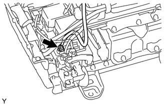
Disconnect the connector of the frame wire No. 3 (high-voltage wire of the power steering converter) from the HV battery junction block.
-
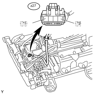
*1 CBPE *2 CEPE Using a megohmmeter set to 500 V, measure the resistance according to the value(s) in the table below.
Note
Be sure to set the megohmmeter to 500 V when performing this test. Using a setting higher than 500 V can result in damage to the component being inspected.
Standard resistance Tester Connection Switch Condition Specified Condition z27-1 (CBPE) - Body ground Power switch off 30 MΩ or higher z27-4 (CEPE) - Body ground Power switch off 30 MΩ or higher
NG
CHECK POWER STEERING CONVERTER WIRE (HV BATTERY JUNCTION BLOCK - POWER STEERING CONVERTER) Click here
OK
-
-
CHECK HV BATTERY JUNCTION BLOCK
CAUTION:
Be sure to wear insulated gloves.
-
Check that the service plug grip is not installed.
-
Remove the HV battery terminal block.
-
*1 Battery Carrier Using a megohmmeter set to 500 V, measure the resistance according to the value(s) in the table below.
Note
Be sure to set the megohmmeter to 500 V when performing this test. Using a setting higher than 500 V can result in damage to the component being inspected.
Standard resistance Tester Connection Condition Specified Condition g2-1 - Battery carrier Power switch off 10 MΩ or higher g3-1 - Battery carrier Power switch off 10 MΩ or higher
OK
REPLACE HYBRID BATTERY TERMINAL BLOCK Click here
NG
REPLACE HV BATTERY JUNCTION BLOCK Click here
-
-
CHECK MOTOR CABLE
CAUTION:
Be sure to wear insulated gloves.
-
Check that the service plug grip is not installed.
-
Disconnect the motor cable from the hybrid vehicle transmission assembly.
Tech Tips
For the removal and installation procedures related to the motor cable, Click here.
-
Using a megohmmeter set to 500 V, measure the resistance according to the value(s) in the table below.
*1 Motor Cable *2 for LHD: *3 for RHD: *4 Shielded Wire Ground Note
Be sure to set the megohmmeter to 500 V when performing this test. Using a setting higher than 500 V can result in damage to the component being inspected.
Standard resistance Tester Connection Switch Condition Specified Condition U - Shielded wire ground Power switch off 100 MΩ or higher V - Shielded wire ground Power switch off 100 MΩ or higher W - Shielded wire ground Power switch off 100 MΩ or higher
OK
REPLACE HYBRID VEHICLE TRANSMISSION ASSEMBLY Click here
NG
REPLACE MOTOR CABLE Click here
-
-
CHECK GENERATOR CABLE
CAUTION:
Be sure to wear insulated gloves.
-
Check that the service plug grip is not installed.
-
Disconnect the generator cable from the hybrid vehicle transmission assembly.
Tech Tips
For the removal and installation procedures related to the generator cable, Click here.
-
Using a megohmmeter set to 500 V, measure the resistance according to the value(s) in the table below.
*1 Generator Cable *2 for LHD: *3 for RHD: *4 Shielded Wire Ground Note
Be sure to set the megohmmeter to 500 V when performing this test. Using a setting higher than 500 V can result in damage to the component being inspected.
Standard resistance Tester Connection Switch Condition Specified Condition U - Shielded wire ground Power switch off 100 MΩ or higher V - Shielded wire ground Power switch off 100 MΩ or higher W - Shielded wire ground Power switch off 100 MΩ or higher
OK
REPLACE HYBRID VEHICLE TRANSMISSION ASSEMBLY Click here
NG
REPLACE GENERATOR CABLE Click here
-
-
CHECK POWER STEERING CONVERTER
CAUTION:
Be sure to wear insulated gloves.
-
Check that the service plug grip is not installed.
-
Disconnect the connector of the frame wire No. 3 (high-voltage wire of the power steering converter) from the HV battery junction block.
-
*1 CBPE *2 CEPE Using a megohmmeter set to 500 V, measure the resistance according to the value(s) in the table below.
Note
Be sure to set the megohmmeter to 500 V when performing this test. Using a setting higher than 500 V can result in damage to the component being inspected.
Standard resistance Tester Connection Switch Condition Specified Condition z27-1 (CBPE) - Body ground Power switch off 30 MΩ or higher z27-4 (CEPE) - Body ground Power switch off 30 MΩ or higher
NG
CHECK POWER STEERING CONVERTER WIRE (HV BATTERY JUNCTION BLOCK - POWER STEERING CONVERTER) Click here
OK
-
-
CHECK HV CONVERTER
CAUTION:
Be sure to wear insulated gloves.
-
Check that the service plug grip is not installed.
-
*1 Hybrid Vehicle Converter Disconnect the hybrid vehicle converter connectors from the HV battery junction block.
Tech Tips
For the removal and installation procedures related to the hybrid vehicle converter connectors, Click here.
-
*1 Hybrid Vehicle Converter Using a megohmmeter set to 500 V, measure the resistance according to the value(s) in the table below.
Note
Be sure to set the megohmmeter to 500 V when performing this test. Using a setting higher than 500 V can result in damage to the component being inspected.
Standard resistance Tester Connection Switch Condition Specified Condition z60-1 (INR) - Hybrid vehicle converter Power switch off 10 MΩ or higher z58-1 (CBD) - Hybrid vehicle converter Power switch off 10 MΩ or higher z59-1 (CED) - Hybrid vehicle converter Power switch off 10 MΩ or higher
NG
REPLACE HV CONVERTER Click here
OK
-
-
CHECK HV BATTERY JUNCTION BLOCK
CAUTION:
Be sure to wear insulated gloves.
-
Check that the service plug grip is not installed.
-
Remove the HV battery terminal block.
-
*1 Battery Carrier Using a megohmmeter set to 500 V, measure the resistance according to the value(s) in the table below.
Note
Be sure to set the megohmmeter to 500 V when performing this test. Using a setting higher than 500 V can result in damage to the component being inspected.
Standard resistance Tester Connection Condition Specified Condition g2-1 - Battery carrier Power switch off 10 MΩ or higher g3-1 - Battery carrier Power switch off 10 MΩ or higher
OK
REPLACE HYBRID BATTERY TERMINAL BLOCK Click here
NG
REPLACE HV BATTERY JUNCTION BLOCK Click here
-
-
CHECK INVERTER WITH CONVERTER ASSEMBLY
CAUTION:
Be sure to wear insulated gloves.
-
Turn the power switch off.
-
Remove the service plug grip. Click here
Note
After removing the service plug grip, do not turn the power switch on (READY) unless instructed by the repair manual because this may cause a malfunction.
-
Remove the inverter terminal cover from the inverter with converter assembly.
-
For LHD vehicles, use the following procedures Click here.
-
For RHD vehicles, use the following procedures Click here.
Note
Lift the inverter terminal cover horizontally so that it does not tilt. Failure to do so may break the inverter cover guide pins.
*1 for LHD: *2 for RHD: -
-
Disconnect the motor cable and generator cable from the inverter with converter assembly.
*1 for LHD: *2 for RHD: -
Remove the connector cover from the inverter with converter assembly.
*1 for LHD: *2 for RHD: Tech Tips
Make sure that no foreign objects have entered or contaminated the inverter with converter assembly.
-
Using a megohmmeter set to 500 V, measure the resistance according to the value(s) in the table below.
*1 for LHD: *2 for RHD: *3 A/C Fuse Note
Be sure to set the megohmmeter to 500 V when performing this test. Using a setting higher than 500 V can result in damage to the component being inspected.
Standard resistance Tester Connection Switch Condition Specified Condition A/C Fuse - Body ground Power switch off 1.0 MΩ or higher Result Result Proceed to OK A NG (for LHD) B NG (for RHD) C
B
REPLACE INVERTER WITH CONVERTER ASSEMBLY Click here
C
REPLACE INVERTER WITH CONVERTER ASSEMBLY Click here
A
-
-
CHECK MOTOR CABLE
CAUTION:
Be sure to wear insulated gloves.
-
Check that the service plug grip is not installed.
-
Disconnect the motor cable from the hybrid vehicle transmission assembly.
Tech Tips
For the removal and installation procedures related to the motor cable, Click here.
-
Using a megohmmeter set to 500 V, measure the resistance according to the value(s) in the table below.
*1 Motor Cable *2 for LHD: *3 for RHD: *4 Shielded Wire Ground Note
Be sure to set the megohmmeter to 500 V when performing this test. Using a setting higher than 500 V can result in damage to the component being inspected.
Standard resistance Tester Connection Switch Condition Specified Condition U - Shielded wire ground Power switch off 100 MΩ or higher V - Shielded wire ground Power switch off 100 MΩ or higher W - Shielded wire ground Power switch off 100 MΩ or higher
NG
REPLACE MOTOR CABLE Click here
OK
-
-
CHECK GENERATOR CABLE
CAUTION:
Be sure to wear insulated gloves.
-
Check that the service plug grip is not installed.
-
Disconnect the generator cable from the hybrid vehicle transmission assembly.
Tech Tips
For the removal and installation procedures related to the generator cable, Click here.
-
Using a megohmmeter set to 500 V, measure the resistance according to the value(s) in the table below.
*1 Generator Cable *2 for LHD: *3 for RHD: *4 Shielded Wire Ground Note
Be sure to set the megohmmeter to 500 V when performing this test. Using a setting higher than 500 V can result in damage to the component being inspected.
Standard resistance Tester Connection Switch Condition Specified Condition U - Shielded wire ground Power switch off 100 MΩ or higher V - Shielded wire ground Power switch off 100 MΩ or higher W - Shielded wire ground Power switch off 100 MΩ or higher
OK
REPLACE HYBRID VEHICLE TRANSMISSION ASSEMBLY Click here
NG
REPLACE GENERATOR CABLE Click here
-
-
CHECK POWER STEERING CONVERTER WIRE (HV BATTERY JUNCTION BLOCK - POWER STEERING CONVERTER)
CAUTION:
Be sure to wear insulated gloves.
-
Check that the service plug grip is not installed.
-
Disconnect the frame wire No. 3 (connector for the HV battery) from the power steering converter.
-
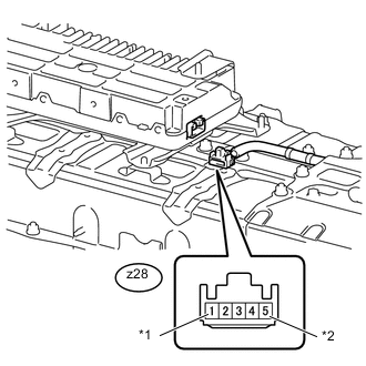
*1 CBP *2 CEP Using a megohmmeter set to 500 V, measure the resistance according to the value(s) in the table below.
Note
Be sure to set the megohmmeter to 500 V when performing this test. Using a setting higher than 500 V can result in damage to the component being inspected.
Standard resistance Tester Connection Switch Condition Specified Condition z28-1 (CBP) - Body ground Power switch off 10 MΩ or higher z28-5 (CEP) - Body ground Power switch off 10 MΩ or higher
OK
REPLACE POWER STEERING CONVERTER Click here
NG
REPLACE POWER STEERING CONVERTER WIRE
-
-
CHECK MOTOR CABLE
CAUTION:
Be sure to wear insulated gloves.
-
Check that the service plug grip is not installed.
-
Disconnect the motor cable from the hybrid vehicle transmission assembly.
Tech Tips
For the removal and installation procedures related to the motor cable, Click here.
-
Using a megohmmeter set to 500 V, measure the resistance according to the value(s) in the table below.
*1 Motor Cable *2 for LHD: *3 for RHD: *4 Shielded Wire Ground Note
Be sure to set the megohmmeter to 500 V when performing this test. Using a setting higher than 500 V can result in damage to the component being inspected.
Standard resistance Tester Connection Switch Condition Specified Condition U - Shielded wire ground Power switch off 100 MΩ or higher V - Shielded wire ground Power switch off 100 MΩ or higher W - Shielded wire ground Power switch off 100 MΩ or higher
OK
REPLACE HYBRID VEHICLE TRANSMISSION ASSEMBLY Click here
NG
REPLACE MOTOR CABLE Click here
-
-
CHECK GENERATOR CABLE
CAUTION:
Be sure to wear insulated gloves.
-
Check that the service plug grip is not installed.
-
Disconnect the generator cable from the hybrid vehicle transmission assembly.
Tech Tips
For the removal and installation procedures related to the generator cable, Click here.
-
Using a megohmmeter set to 500 V, measure the resistance according to the value(s) in the table below.
*1 Generator Cable *2 for LHD: *3 for RHD: *4 Shielded Wire Ground Note
Be sure to set the megohmmeter to 500 V when performing this test. Using a setting higher than 500 V can result in damage to the component being inspected.
Standard resistance Tester Connection Switch Condition Specified Condition U - Shielded wire ground Power switch off 100 MΩ or higher V - Shielded wire ground Power switch off 100 MΩ or higher W - Shielded wire ground Power switch off 100 MΩ or higher
OK
REPLACE HYBRID VEHICLE TRANSMISSION ASSEMBLY Click here
NG
REPLACE GENERATOR CABLE Click here
-