HYBRID CONTROL SYSTEM, Diagnostic DTC:P0A94-442
| DTC Code | DTC Name |
|---|---|
| P0A94-442 | DC / DC Converter Performance |
DESCRIPTION
The boost converter boosts the 288 V DC from the HV battery to a maximum of approximately 650 V DC. The inverter converts the voltage that has been boosted by the boost converter into alternating current, which is used for driving MG2 and MG1. When a motor generator operates as a generator, the alternating current that it creates is converted into direct current by the inverter. Then the boost converter drops this voltage to direct current of approximately 288 V in order to charge the HV battery.
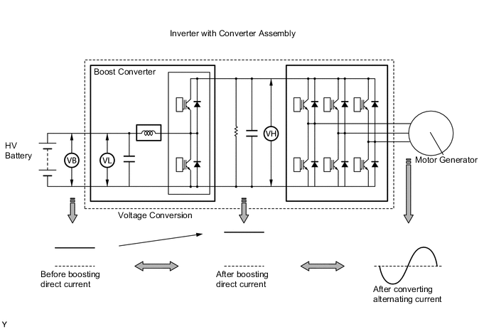
The MG ECU uses a voltage sensor (VL) that is built into the boost converter to detect the high voltage before it is boosted. It also uses a voltage sensor (VH) that is built into the inverter to detect the high voltage after it is boosted. Based on the voltage before and after it is boosted, the MG ECU controls the operation of the boost converter to boost the voltage to the target voltage.
| DTC No. | INF Code | DTC Detection Condition | Trouble Area |
|---|---|---|---|
| P0A94 | 442 | Abnormal voltage execution value | Inverter with converter assembly |
PROCEDURE
-
CHECK DTC OUTPUT (HV)
-
Connect the intelligent tester to the DLC3.
-
Turn the power switch on (IG).
-
Select the following menu items: Powertrain / Hybrid Control / Trouble Codes.
-
Check if DTCs are output.
Result Result Proceed to P0A94-442 only is output. A P3240-443 is also output. *1 A Any of the following DTCs are also output. B DTC No. Relevant Diagnosis P0A1A (all INF codes) *2 Generator Control Module P0A1B (all INF codes) *2 Drive Motor "A" Control Module P0A1D (all INF codes) *2 Hybrid Powertrain Control Module P0A3F-243 Drive Motor "A" Position Sensor Circuit P0A40-500 Drive Motor "A" Position Sensor Circuit Range / Performance P0A41-245 Drive Motor "A" Position Sensor Circuit Low P0A4B-253 Generator Position Sensor Circuit P0A4C-513 Generator Position Sensor Circuit Range / Performance P0A4D-255 Generator Position Sensor Circuit Low P0A60 (all INF codes) *2 Drive Motor "A" Phase V Current P0A63 (all INF codes) *2 Drive Motor "A" Phase W Current P0A72 (all INF codes) *2 Generator Phase V Current P0A75 (all INF codes) *2 Generator Phase W Current P0A78-266, 267, 279, 287, 503, 504, 505, 506, 586, 806, 807, 808 Drive Motor "A" Inverter Performance P0A7A-325, 517, 518, 809, 810, 811 Generator Inverter Performance P0A90-509 Drive Motor "A" Performance P0A92-521 Hybrid Generator Performance P0A94-547, 548, 549, 554, 555, 556, 585, 587, 589, 590 DC / DC Converter Performance P0C76-523 Hybrid Battery System Discharge Time Too Long Note
*1: If P3240-443 is also output, be sure to replace the inverter with converter assembly after troubleshooting and performing repairs for all output DTCs.
Tech Tips
-
*2: If any INF codes are output for this DTC, refer to the corresponding diagnostic flowchart.
-
P0A94-442 may be set due to a malfunction which also causes DTCs in the preceding table to be set. In this case, first troubleshoot the output DTCs in the preceding table. Then, perform a test to attempt to reproduce the problems, and check that no DTCs are output.
-
B 
GO TO DTC CHART Click here
A 
-
-
CHECK CONNECTOR CONNECTION CONDITION (INVERTER WITH CONVERTER ASSEMBLY CONNECTOR)
Note
Before disconnecting the connector, confirm that it is properly connected by checking that the locking claws are engaged and that the connector cannot be pulled out.
-
Check the connection of the low voltage connector of the inverter with converter assembly.
OK The connector is connected securely and there are no contact problems. Tech Tips
When connecting the connector, insert it with the locking lever in the raised position. Rotate the lever downward and make sure that the connector is pulled into its socket. When the locking lever is in its fully closed position, a click will be heard as its locking claws engage. After the click is heard, pull up on the connector to confirm that it is properly connected.
Result Result Proceed to OK (for LHD) A OK (for RHD) B NG C
A
REPLACE INVERTER WITH CONVERTER ASSEMBLY Click here
B
REPLACE INVERTER WITH CONVERTER ASSEMBLY Click here
C
CONNECT SECURELY
-