HYBRID CONTROL SYSTEM, Diagnostic DTC:P0A0D-350, P0A0D-351
| DTC Code | DTC Name |
|---|---|
| P0A0D-350 | High Voltage System Inter-Lock Circuit High |
| P0A0D-351 | High Voltage System Inter-Lock Circuit High |
DESCRIPTION
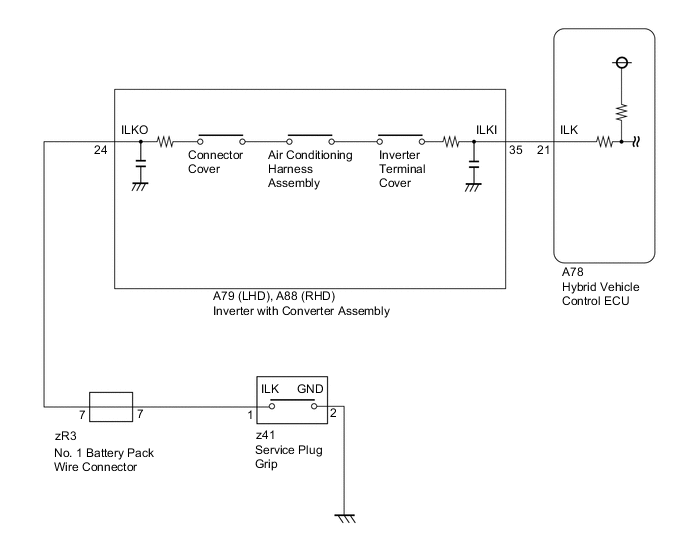
When the hybrid vehicle control ECU detects that a safety device is operated, it will prohibit hybrid system operation or shut off the system main relay. There are four safety devices in four different locations. The first safety device is located at the service plug grip. The second one is located at the connector cover of the inverter with converter assembly. The third one is located at the air conditioning harness assembly that is connected to the inverter with converter assembly. The fourth one is located at the inverter terminal cover where the motor and generator cables are connected to the inverter with converter assembly. If the service plug grip, inverter with converter assembly connector cover, inverter terminal cover, or air conditioning harness assembly is removed, the interlock signal line will be opened. If the vehicle is being driven, this condition will be determined to be an open circuit and the system main relays will not be shut off. If the safety devices are reinstalled correctly, the system will return to normal when the power switch is turned on (IG).
| DTC No. | INF Code | DTC Detection Condition | Trouble Area |
|---|---|---|---|
| P0A0D | 350 | Operating any of the safety devices with the vehicle stopped (ILK signal is ON) and turning the power switch on (IG) |
|
| P0A0D | 351 | Interlock signal line opens (ILK signal is ON) while the vehicle is being driven |
WIRING DIAGRAM
CAUTION / NOTICE / HINT
CAUTION:
-
Before inspecting the high-voltage system or disconnecting the low voltage connector of the inverter with converter assembly, take safety precautions such as wearing insulated gloves and removing the service plug grip to prevent electrical shocks. After removing the service plug grip, put it in your pocket to prevent other technicians from accidentally reconnecting it while you are working on the high-voltage system.
-
After disconnecting the service plug grip, wait for at least 10 minutes before touching any of the high-voltage connectors or terminals. After waiting for 10 minutes, check the voltage at the terminals in the inspection point in the inverter with converter assembly. The voltage should be 0 V before beginning work.
Tech Tips
Waiting for at least 10 minutes is required to discharge the high-voltage capacitor inside the inverter with converter assembly.
PROCEDURE
-
CHECK DTC OUTPUT (HV)
-
Connect the intelligent tester to the DLC3.
-
Turn the power switch on (IG).
-
Select the following menu items: Powertrain / Hybrid Control / Trouble Codes.
-
Check if DTCs are output.
Result Result Proceed to P0A0D only is output. A P0A1D is output (Except for INF code 390) B
B 
GO TO DTC CHART Click here
A 
-
-
CLEAR DTC (HV)
-
Select the following menu items: Powertrain / Hybrid Control / Trouble Codes.
-
Read and record the DTCs and freeze frame data.
-
Select the following menu items: Powertrain / Hybrid Control / Trouble Codes.
-
Check if DTCs are output.
NEXT
-
-
CHECK DTC OUTPUT (HV)
-
Select the following menu items: Powertrain / Hybrid Control / Trouble Codes.
-
Check if DTCs are output.
Result Result Proceed to P0A0D-350 or P0A0D-351 is output again. A Neither P0A0D-350 nor P0A0D-351 is output again. B
B 
CHECK CONNECTOR CONNECTION CONDITION (INTERLOCK CIRCUIT) Click here
A
-
-
CHECK SERVICE PLUG GRIP
CAUTION:
Be sure to wear insulated gloves.
-
Check if the service plug grip is installed correctly.
Tech Tips
-
For the removal and installation procedures, Click here.
-
P0A0D-350 is also set if the power switch is turned on (IG) with the service plug grip removed. Confirm the conditions when the malfunction occurred.
-
NG
CONNECT SECURELY
OK
-
-
CHECK INVERTER TERMINAL COVER
CAUTION:
Be sure to wear insulated gloves.
-
Turn the power switch off.
-
Remove the service plug grip Click here.
Note
After removing the service plug grip, do not turn the power switch on (READY) unless instructed by the repair manual because this may cause a malfunction.
-
Check if the inverter terminal cover of the inverter with converter assembly is installed correctly.
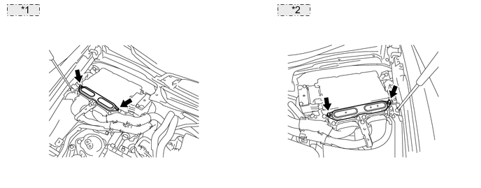
*1 for LHD: *2 for RHD: OK The inverter terminal cover is installed correctly.
NG
CONNECT SECURELY
OK
-
-
CHECK INVERTER WITH CONVERTER ASSEMBLY
CAUTION:
Be sure to wear insulated gloves.
-
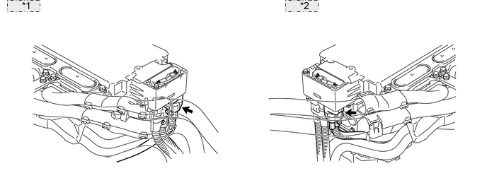
Check if the connector cover of the inverter with converter assembly is installed correctly.
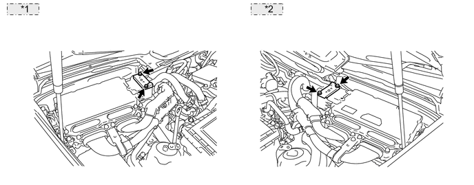
*1 for LHD: *2 for RHD: OK The connector cover is installed correctly.
NG
CONNECT SECURELY
OK
-
-
CHECK AIR CONDITIONING HARNESS ASSEMBLY
CAUTION:
Be sure to wear insulated gloves.
-
Check if the air conditioning harness assembly connector is connected correctly.
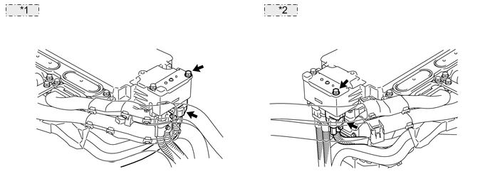
*1 for LHD: *2 for RHD: OK The air conditioning harness assembly connector is connected correctly.
NG
CONNECT SECURELY
OK
-
-
CHECK HYBRID VEHICLE CONTROL ECU
CAUTION:
Be sure to wear insulated gloves.
-
Turn the power switch off.
-
Check that the service plug grip is not installed.
Note
After removing the service plug grip, do not turn the power switch on (READY), unless instructed by the repair manual because this may cause a malfunction.
-
Disconnect the low voltage connector from the inverter with converter assembly.
-
Turn the power switch on (IG).
-
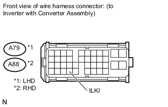
Measure the voltage according to the value(s) in the table below.
Standard voltage LHD Tester Connection Switch Condition Specified Condition A79-35 (ILKI) - Body ground Power switch on (IG) 11 to 14 V RHD Tester Connection Switch Condition Specified Condition A88-35 (ILKI) - Body ground Power switch on (IG) 11 to 14 V
NG
CHECK HARNESS AND CONNECTOR (HYBRID VEHICLE CONTROL ECU - INVERTER WITH CONVERTER ASSEMBLY) Click here
OK
-
-
CHECK INVERTER WITH CONVERTER ASSEMBLY
CAUTION:
Be sure to wear insulated gloves.
-
Turn the power switch off.
-
Check that the service plug grip is not installed.
Note
After removing the service plug grip, do not turn the power switch on (READY) unless instructed by the repair manual because this may cause a malfunction.
-
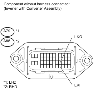
Measure the resistance according to the value(s) in the table below.
Standard resistance LHD Tester Connection Switch Condition Specified Condition A79-35 (ILKI) - A79-24 (ILKO) Power switch off Less than 10 Ω RHD Tester Connection Switch Condition Specified Condition A88-35 (ILKI) - A88-24 (ILKO) Power switch off Less than 10 Ω
NG
CHECK INVERTER TERMINAL COVER Click here
OK
-
-
CHECK HARNESS AND CONNECTOR (INVERTER WITH CONVERTER ASSEMBLY - NO. 1 BATTERY PACK WIRE CONNECTOR)
-
Connect the low voltage connector of the inverter with converter assembly.
-
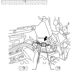
*1 No. 1 Battery Pack Wire Connector *2 B Side *3 A Side Disconnect the No. 1 battery pack wire connector.
Tech Tips
For the removal and installation procedures related to the No. 1 battery pack wire connector, Click here.
-
Turn the power switch on (IG).
-
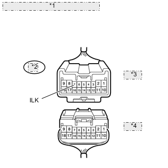
*1 No. 1 Battery Pack Wire Connector *2 zR3 *3 A Side *4 B Side Measure the voltage according to the value(s) in the table below.
Standard voltage Tester Connection Switch Condition Specified Condition zR3-7 (ILK) - Body ground Power switch on (IG) 11 to 14 V
NG
REPAIR OR REPLACE HARNESS OR CONNECTOR
OK
-
-
CHECK HARNESS AND CONNECTOR (NO. 1 BATTERY PACK WIRE CONNECTOR - BODY GROUND)
-
*1 No. 1 Battery Pack Wire Connector *2 zR3 *3 A Side *4 B Side Measure the resistance according to the value(s) in the table below.
Standard resistance Tester Connection Switch Condition Specified Condition zR3-7 (ILK) - Body ground Power switch off Below 1 Ω
NG
CHECK SERVICE PLUG GRIP Click here
OK
-
-
CHECK CONNECTOR CONNECTION CONDITION (INTERLOCK CIRCUIT)
-
Check the connections of each connector.
OK Dirt or foreign objects have not entered the connection, and there is no evidence of contamination.
OK
REPLACE HYBRID VEHICLE CONTROL ECU Click here
NG
REPAIR OR REPLACE CONNECTOR
-
-
CHECK SERVICE PLUG GRIP
-
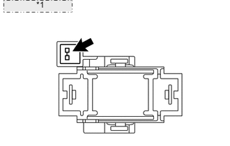
*1 Service Plug Grip Check the condition of the service plug grip interlock.
OK Dirt or foreign objects have not entered the connection, and there is no evidence of contamination.
NG
REPLACE SERVICE PLUG GRIP Click here
OK
-
-
CHECK HARNESS AND CONNECTOR
-
Check that the interlock connector at the service plug grip installation socket is connected correctly.
OK The connector is connected correctly.
NG
CONNECT SECURELY
OK
-
-
CHECK HARNESS AND CONNECTOR (NO. 1 BATTERY PACK WIRE CONNECTOR - SERVICE PLUG GRIP)
CAUTION:
Be sure to wear insulated gloves.
-
Measure the resistance according to the value(s) in the table below.
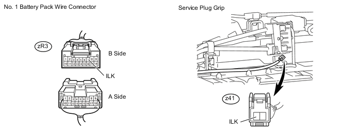
Standard resistance Tester Connection Switch Condition Specified Condition zR3-7 (ILK) - z41-1 (ILK) Power switch off Below 1 Ω
OK
REPAIR OR REPLACE HARNESS OR CONNECTOR
NG
REPAIR OR REPLACE HARNESS OR CONNECTOR
-
-
CHECK INVERTER TERMINAL COVER
CAUTION:
Be sure to wear insulated gloves.
-
Turn the power switch off.
-
Check that the service plug grip is not installed.
Note
After removing the service plug grip, do not turn the power switch on (READY) unless instructed by the repair manual because this may cause a malfunction.
-
Remove the inverter terminal cover from the inverter with converter assembly.
-
For LHD vehicles, use the following procedures Click here.
-
For RHD vehicles, use the following procedures Click here.
Note
Lift the inverter terminal cover horizontally so that it does not tilt. Failure to do so may break the inverter cover guide pins.
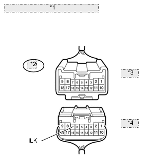
*1 for LHD: *2 for RHD: -
-
Check the condition of the inverter terminal cover interlock.
OK Dirt or foreign objects have not entered the connection, and there is no evidence of contamination. 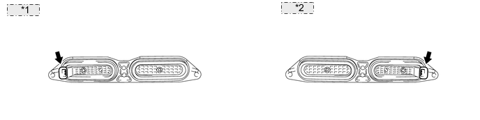
*1 for LHD: *2 for RHD: Result Result Proceed to OK A NG (for LHD) B NG (for RHD) C
B
REPLACE INVERTER TERMINAL COVER Click here
C
REPLACE INVERTER TERMINAL COVER Click here
A
-
-
CHECK INVERTER WITH CONVERTER ASSEMBLY (CONNECTOR COVER ASSEMBLY OF INVERTER WITH CONVERTER ASSEMBLY)
CAUTION:
Be sure to wear insulated gloves.
-
Turn the power switch off.
-
Check that the service plug grip is not installed.
Note
After removing the service plug grip, do not turn the power switch on (READY) unless instructed by the repair manual because this may cause a malfunction.
-
Remove the connector cover from the inverter with converter assembly.
*1 for LHD: *2 for RHD: -
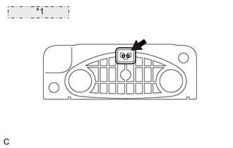
*1 Connector Cover Check the condition of the connector cover interlock.
OK Dirt or foreign objects have not entered the connection, and there is no evidence of contamination. Result Result Proceed to OK A NG (for LHD) B NG (for RHD) C
B
REPLACE INVERTER WITH CONVERTER ASSEMBLY Click here
C
REPLACE INVERTER WITH CONVERTER ASSEMBLY Click here
A
-
-
CHECK AIR CONDITIONING HARNESS ASSEMBLY (AIR CONDITIONING HARNESS ASSEMBLY CONNECTOR)
CAUTION:
Be sure to wear insulated gloves.
-
Disconnect the air conditioning harness assembly from the inverter with converter assembly.
*1 for LHD: *2 for RHD: -
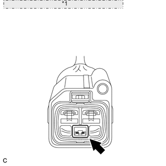
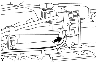
*1 Front view of wire harness connector: (to Air Conditioning Harness Assembly) Check the condition of the air conditioning harness assembly interlock.
OK Dirt or foreign objects have not entered the connection, and there is no evidence of contamination. Result Result Proceed to OK (for LHD) A OK (for RHD) B NG C
A
REPLACE INVERTER WITH CONVERTER ASSEMBLY Click here
B
REPLACE INVERTER WITH CONVERTER ASSEMBLY Click here
C
REPLACE AIR CONDITIONING HARNESS ASSEMBLY
-
-
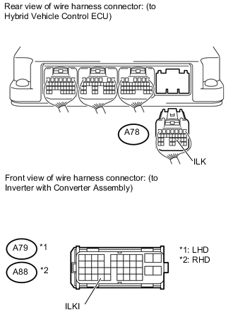
CHECK HARNESS AND CONNECTOR (HYBRID VEHICLE CONTROL ECU - INVERTER WITH CONVERTER ASSEMBLY)
-
Turn the power switch off.
-
Disconnect connector A78 from the hybrid vehicle control ECU.
-
Measure the resistance according to the value(s) in the table below.
Standard resistance LHD Tester Connection Switch Condition Specified Condition A78-21 (ILK) - A79-35 (ILKI) Power switch off Below 1 Ω RHD Tester Connection Switch Condition Specified Condition A78-21 (ILK) - A88-35 (ILKI) Power switch off Below 1 Ω
OK
REPLACE HYBRID VEHICLE CONTROL ECU Click here
NG
REPAIR OR REPLACE HARNESS OR CONNECTOR
-