HYBRID CONTROL SYSTEM SYSTEM DESCRIPTION
-
BASIC OPERATION
-
This system generates a motive force by combination the engine, MG1, and MG2 in accordance with the driving conditions. Representative examples of the various combinations are described below.
-
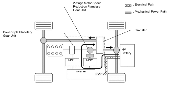
Supply of electrical power from the HV battery to MG2 provides force to drive the wheels.
-
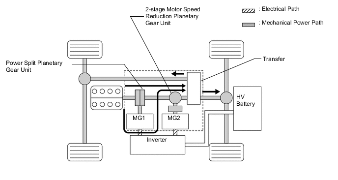
While the wheels are being driven by the engine via the planetary gears, MG1 is also being driven by the engine via the power split planetary gear unit, in order to supply the electricity that MG1 generates to MG2.
-
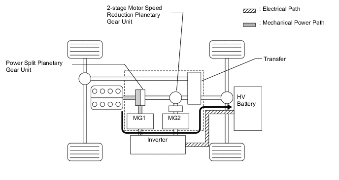
MG1 is also driven by the engine via the planetary gears, in order to charge the HV battery.
-
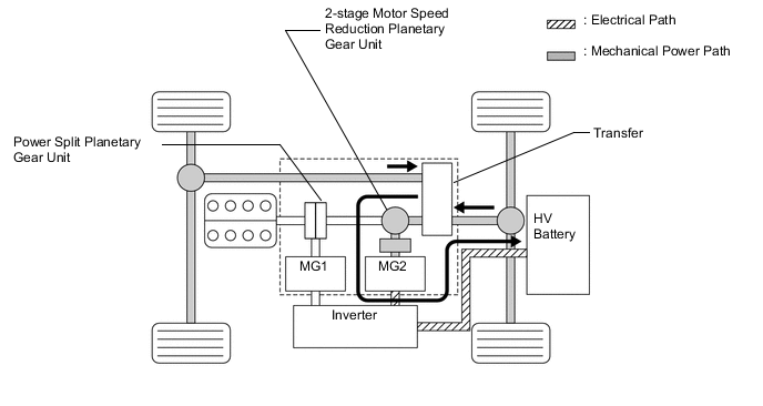
When the vehicle is decelerating, kinetic energy from the wheels is recovered and converted into electrical energy by means of MG2, and used to recharge the HV battery.
-
-
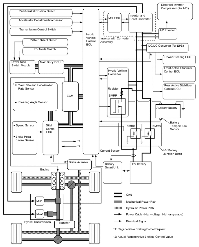
SYSTEM DIAGRAM
-
FUNCTION OF MAIN COMPONENTS
Item Outline Hybrid Vehicle Transmission Assembly MG1
-
MG1, which is driven by the engine, generates high-voltage electricity in order to operate MG2 or charge the HV battery. Also, it functions as a starter to start the engine.
-
MG1 operates so that the gear ratio of the power split planetary gear unit will optimally suit the driving conditions of the vehicle.
MG2
-
Driven by electrical power from MG1 or the HV battery, and generates motive force for the wheels.
-
During braking, or when the accelerator pedal is not depressed, it generates electricity to recharge the HV battery (Regenerative braking control).
Power Split Planetary Gear Unit Distributes the engine's drive force as appropriate to directly drive the vehicle as well as drive MG1. 2-stage Motor Speed Reduction Planetary Gear Unit Reduces the rotational speed of MG2 in accordance with the characteristics of the planetary gear set, in order to increase torque. Furthermore, it shifts the transmission in two stages in accordance with the conditions of the vehicle. HV Battery Unit HV Battery
Hybrid Vehicle Converter
-
Supplies electrical power the MG1 and MG2 in accordance with the driving conditions of the vehicle.
-
Recharged by the MG1 and MG2 in accordance with the SOC and the driving conditions of the vehicle.
DC/DC Converter
(For Auxiliary Battery)
Converts a voltage of DC 288 V to DC14 V in order to supply electricity to body electrical components, as well as to recharge the auxiliary battery (DC 14 V). Contains SMRP. DC/DC Converter
(For EPS and Active Stabilizer Suspension System*1)
-
Converts a voltage of DC 288 V to DC 46 V in order to supply electricity to the EPS and active stabilizer suspension systems*1.
-
If high voltage power supply to the EPS fails, the DC/DC converter boosts the auxiliary battery voltage from 12 V to 33 V and supplies it to the power steering ECU (EPS).
Battery Smart Unit Monitors the conditions of the HV battery and transmits this information to the hybrid vehicle control ECU. Service Plug Grip Shuts off the high-voltage circuit of the HV battery when this plug grip is removed for vehicle inspection or maintenance. Inverter with Converter Assembly Inverter with Converter Assembly Converts the high-voltage DC (HV battery) into AC (MG1 and MG2) and vice versa (converts AC into DC). Boost Converter Boosts the nominal voltage of the HV battery from DC 288 V to DC 650V and vice versa (drops DC 650 V to DC 288 V). MG ECU Controls the inverter and boost converter in accordance with the signals received from the hybrid vehicle control ECU, thus driving MG1 or MG2 or causing them to generate electricity. Hybrid Vehicle Control ECU Effects comprehensive control of the THS II.
-
Information from each sensor as well as from the ECU (battery smart unit, skid control ECU, power steering ECU, front active stabilizer control ECU*1, and rear active stabilizer control ECU*1) is received, and based on this information, the required torque and output power is calculated. The hybrid vehicle control ECU sends the calculated result to the inverter with converter assembly and skid control ECU.
-
Monitors the charging condition of the HV battery.
-
Transmits signals to the air conditioning ECU that controls the dedicated cooling system for the HV battery or the rear air conditioning system*2in order to perform the HV battery control.
-
Controls the hybrid vehicle converter (DC/DC converter) for the auxiliary battery and the DC/DC converter for the EPS or active stabilizer suspension system.
ECM Activates the ETCS-i in accordance with the target engine speed and required engine motive force received from the hybrid vehicle control ECU. Skid Control ECU
-
During braking, the skid control ECU calculates the regenerative braking force that is required for control and transmits it to the hybrid vehicle control ECU.
-
Calculates the motive force that is required for control during the operation of TRAC or VSC and transmits it to the hybrid vehicle control ECU.
Accelerator Pedal Position Sensor Converts the accelerator pedal position into an electrical signal and outputs it to the hybrid vehicle control ECU. Park/Neutral Position Switch Converts the shift position into an electrical signal and outputs it to the hybrid vehicle control ECU. HV Battery Junction Block Connects and disconnects the high-voltage power circuit between the HV battery and inverter with converter assembly, through the use of a signal from the hybrid vehicle control ECU. Contains SMRB and SMRG. Interlock Circuit
(for Inverter Cover and Service Plug Grip)
Verifies that the cover of both the inverter and the service plug grip have been installed. Auxiliary Battery Charged by the HV battery module power via the hybrid vehicle converter (DC/DC converter) for the auxiliary battery. Supplies power to the audio system, air conditioning system (except the electric inverter compressor) and the ECUs. *1: Models with active stabilizer suspension system
*2: Models with rear air conditioning system
-